3OM-1343-008_w.pdf - 第234页
6-3 AKFEDT -ID 2. Machine System When the [MACH. SYS.] button on the "MACH SET" menu bar is pressed, the following window appears. Fig. 3F2 "System" Window Note The displayed window will look dif fere…

6-2
AKFEDT-ID
"MACH SET" Menu Bar
The following buttons are arranged and used to open the operation
windows and set up the system environment.
Table 3F1
Menu Buttons Description
MACH. SYS.
This enables the operator to set the offset data, the automatic operation
data, the light tower, and the alarm system.
NOZ. DATA
This enables the operator to set the placement head/nozzle data and
the nozzle data.
MACH SETUP
This enables the operator to set the screen saver function, specify the
unit of length, and enable or disable the data editing under production
operation.
PASSWORD
This enables the operator to set a password and the scope of authority
according to the given authority.
DATE & TIME
This enables the operator to set the system clock (year, month, day,
hours, minutes, and seconds) of the machine.
NETWK. DT.
This enables the operator to set up the network environment.
MON. ADJ
This enables the operator to adjust the monitor.
0601-002
1. Menus for System Setting
6-3
AKFEDT-ID
2. Machine System
When the [MACH. SYS.] button on the "MACH SET" menu bar is pressed,
the following window appears.
Fig. 3F2 "System" Window
Note
The displayed window will look different, depending on which option is
selected.
The "System" window has the following tab sheets. When a tab is pressed,
the corresponding tab sheet appears.
Table 3F2
Tabs Description
Device Offset
The corresponding tab sheet enables the operator to set various kinds
of offset data for positional adjustment and accuracy of each device
section related to machine operation.
Auto Operation
The corresponding tab sheet enables the operator to set various
parameters related to automatic operation of the machine and check
the machine performance, production rate, production guidance, etc.
Confi guration Setup
The corresponding tab sheet enables the operator to set up parameters
related to the light tower and the buzzer.
0607-003
2. Machine System
6-4
AKFEDT-ID
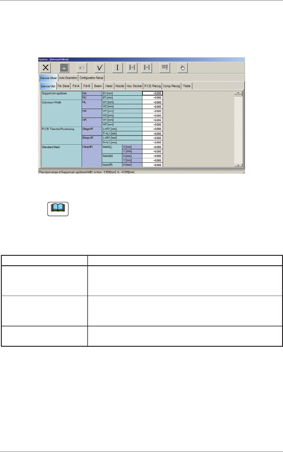
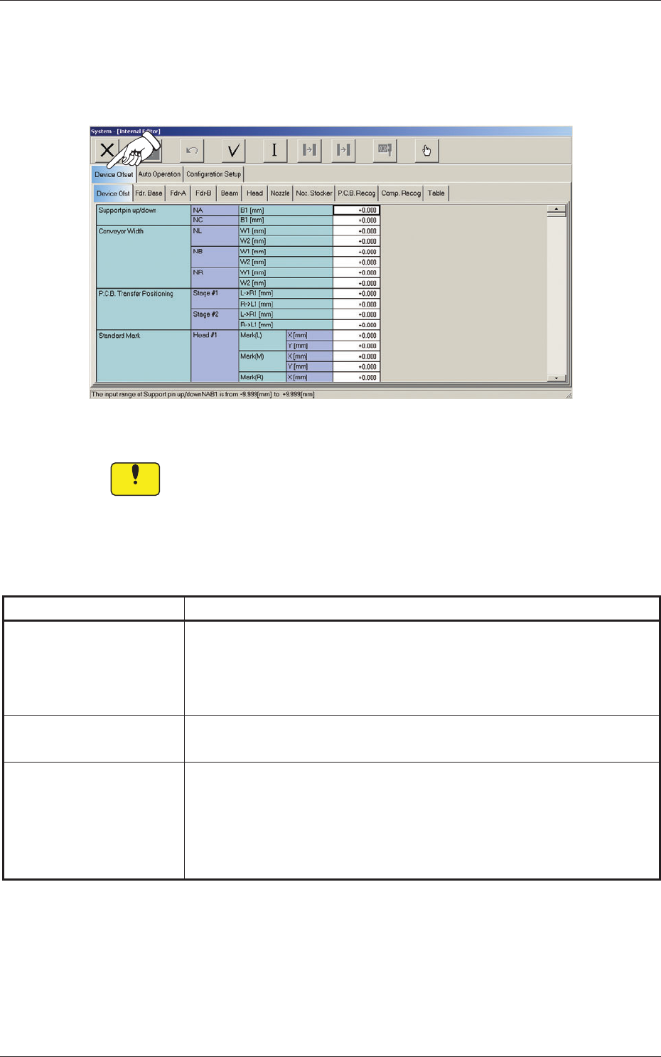
2.1 Device Offset Data
When the "Device Offset" tab is pressed in the "System - [Internal Editor]"
window, the following tab sheet appears.
Fig. 3F3 "Device Offset" Tab Sheet
Notice
Do not change the parameters unless necessary. These parameters
are factory-adjusted upon shipment of the machine.
The "Device Offset" tab is provided with the following tabs. When each tab
is pressed, the corresponding tab sheet appears.
Table 3F3-1
Tabs Description
Device Ofst
The corresponding tab sheet enables the operator to adjust the positional
and angular deviations based on the design dimensions representing the
X/Y beam driving X/Y coordinates viewed from the PCB positioning
X/Y coordinates.
Fdr. Base
The corresponding tab sheet enables the operator to adjust the deviations
based on the design values of each individual feeders.
Fdr-A
This offset data is used independently for the machine. The corresponding
tab sheet enables the operator to adjust the positional deviations (viewed
from the PCB positioning X and Y coordinates) based on the design
dimensions representing the feeder pickup position and height for each
individual feeder slot Nos. (Fdr Nos.).
0607-003
2.1 Device Offset Data