3OM-1343-008_w.pdf - 第238页
6-7 AKFEDT -ID [5] [6] Fig. 3F6 "Device Offset" T ab Sheet (3) [8] [7] Fig. 3F7 "Device Offset" T ab Sheet (4) [10] [9] Fig. 3F8 "Device Offset" T ab Sheet (5) 0607-003 2.1 Device Offset Dat…

6-6
AKFEDT-ID
0607-003
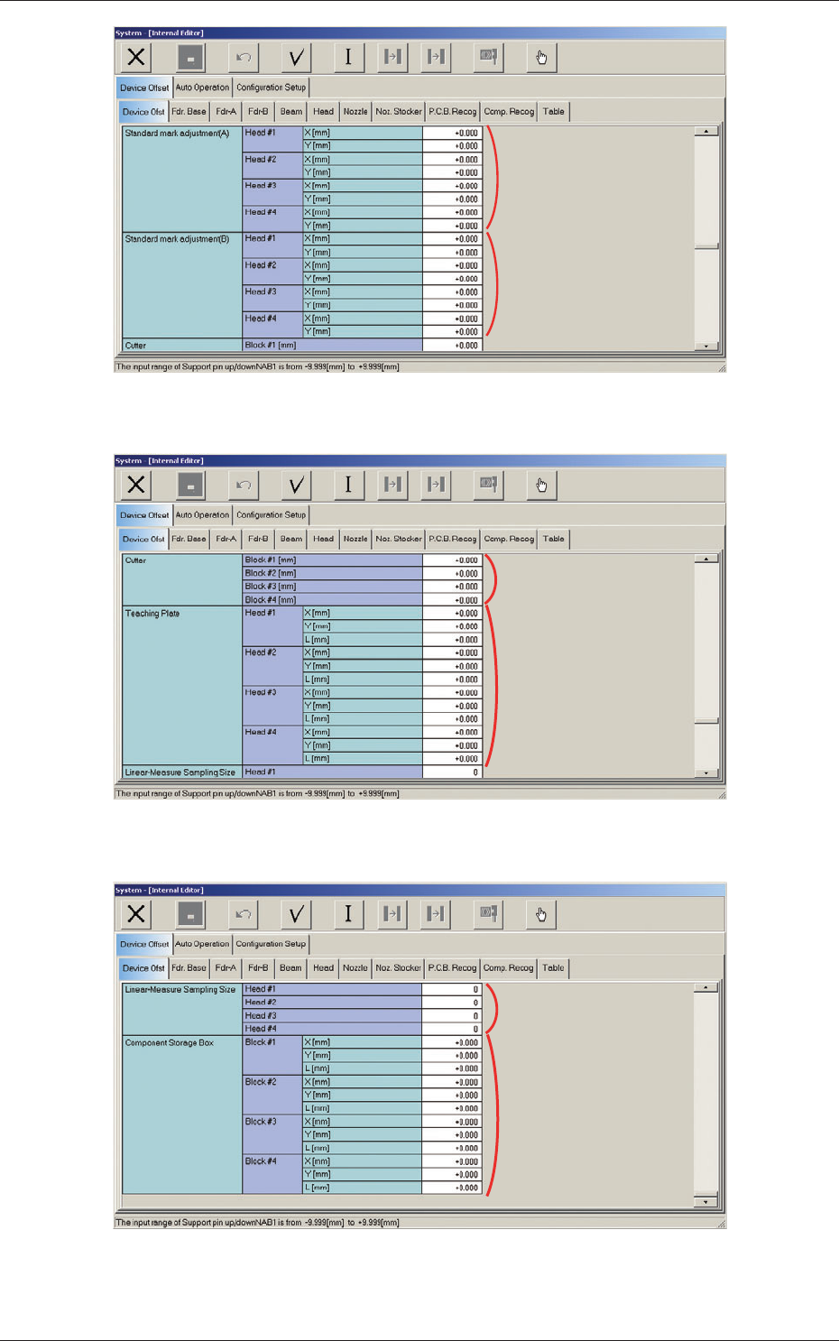
2.1.1 Device Offset
When the "Device Ofst" tab is pressed in the "Device Offset" tab sheet, the
following tab sheet appears.
[1]
[2]
[3]
Fig. 3F4 "Device Offset" Tab Sheet (1)
[4]
Fig. 3F5 "Device Offset" Tab Sheet (2)
2.1 Device Offset Data
6-7
AKFEDT-ID
[5]
[6]
Fig. 3F6 "Device Offset" Tab Sheet (3)
[8]
[7]
Fig. 3F7 "Device Offset" Tab Sheet (4)
[10]
[9]
Fig. 3F8 "Device Offset" Tab Sheet (5)
0607-003
2.1 Device Offset Data
6-8
AKFEDT-ID
[1] Support pin up/down
NA and NC
B1 [mm]
This is the offset data for the origin position of the support pin up/down
axis which ascends or descends during PCB positioning.
A plus (+) value decreases the ascending stroke during PCB positioning.
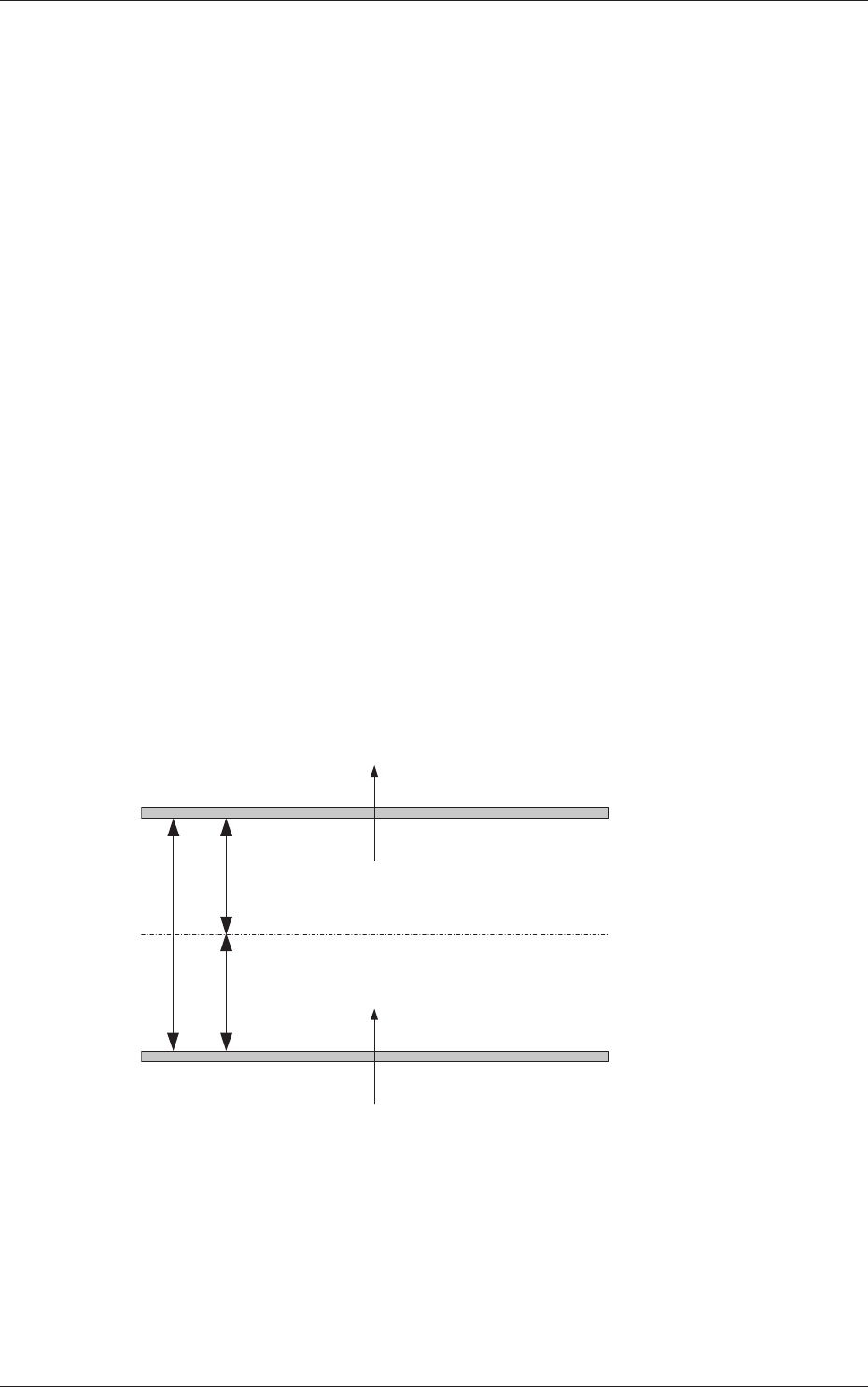
[2] Conveyor Width
NL, NB and NR
W1 and W2 [mm]
This offset is used to adjust the conveyor width to the absolute values.
When the conveyor width is set up to the specifi ed one based on
the positioning center, a difference will be caused in the dimension
between the actually measured value (the distance between the machine
positioning center and each chute) and the half of the specifi ed width. In
this case, enter the difference in each text box.
W1 Offset :
A plus value must be entered when the actually
measured width is narrower than the half of the
specifi ed one.
W2 Offset :
A minus value must be entered when the actually
measured width is narrower than the half of the
specifi ed one.
A
A/2
A/2
NL-W1
NR-W1
NB-W1
NL-W2
NR-W2
NB-W2
(+)
(-)
(+)
(-)
Fig. 3F9
0607-003
2.1 Device Offset Data