3OM-1343-008_w.pdf - 第252页
6-21 AKFEDT -ID 0607-003 2.1.6 Head (B) Offset When the "Head" tab is pressed in the "Device Offset" tab sheet and the "Hd-B" tab is selected, the following tab sheet appears. Fig. 3F20 &quo…
6-20
AKFEDT-ID
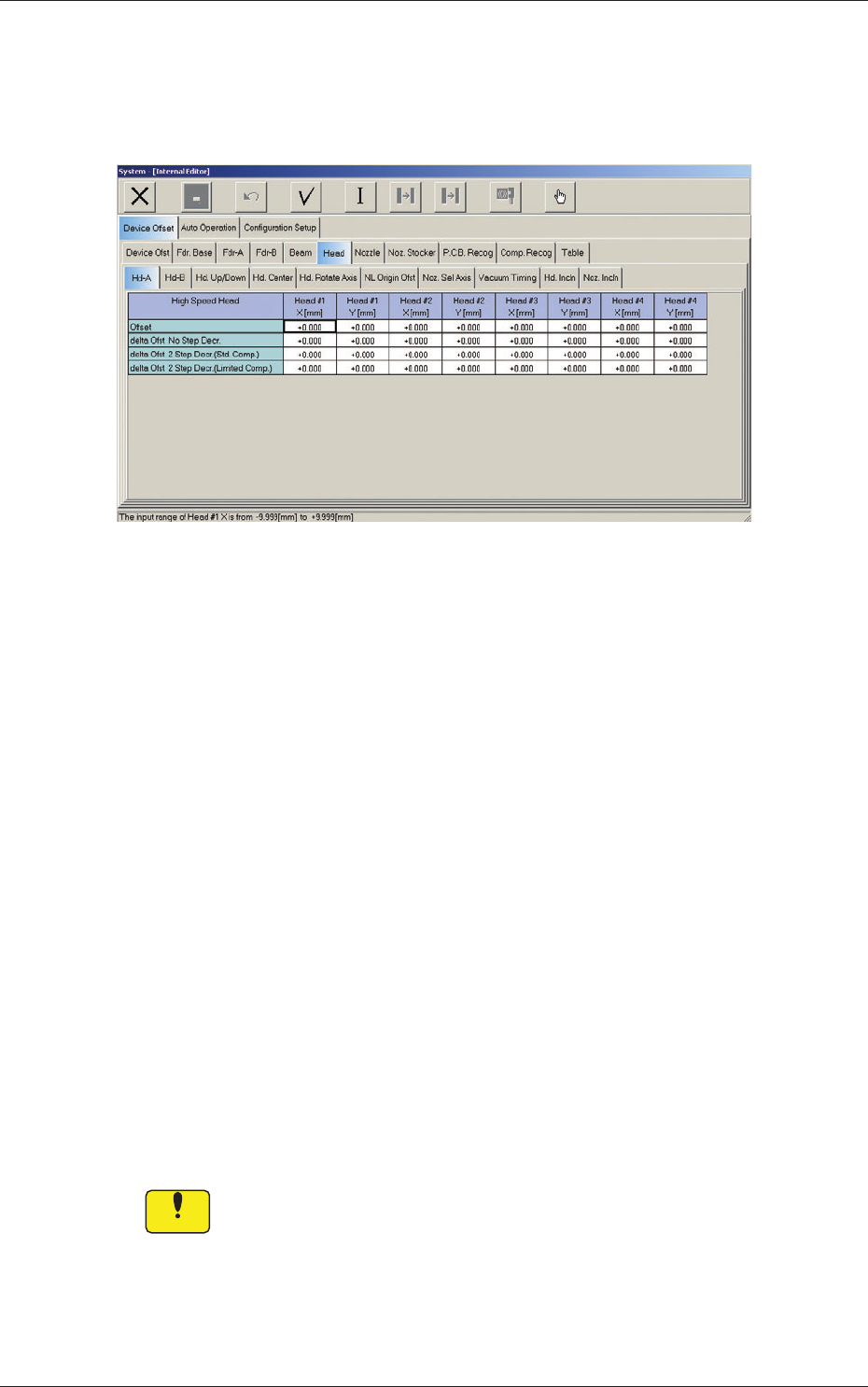
2.1.5 Head (A) Offset
When the "Head" tab is pressed in the "Device Offset" tab sheet and the
"Hd-A" tab is selected, the following tab sheet appears.
Fig. 3F16 "Head-A" Tab Sheet
Head 1, Head 2, Head 3, Head 4
X, Y [mm]
[1] Offset
The set parameters are used to adjust the deviations of the head
rotational centers caused due to the movement of the head U/D axes.
[2] delta Ofst No. Step Decr.
When no speed deceleration for component placement is specifi ed in
the library data and the position for the placement is calculated, the
proper deceleration rate is converted and added.
[3] delta Ofst 2 Step Decr. (Std. Comp.)
When a standard component is selected in the library data and the
position for the placement is calculated, the proper deceleration rate is
converted and added.
[4] delta Ofst 2 Step Decr. (Limited Comp.)
When a limited (special) component is selected in the library data and
the position for the placement is calculated, the proper deceleration rate
is converted and added.
Notice
Do not change the parameters unless necessary. They are factory-specifi ed
upon shipment of the machine.
2.1 Device Offset Data
0607-004
6-21
AKFEDT-ID
0607-003
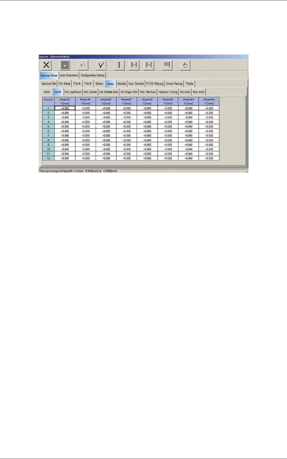
2.1.6 Head (B) Offset
When the "Head" tab is pressed in the "Device Offset" tab sheet and the
"Hd-B" tab is selected, the following tab sheet appears.
Fig. 3F20 "Head-B" Tab Sheet
Nozzles 1 through 12
Head #1, Head #2, Head #3, and Head #4
X (Horizontal) and Y (Vertical) [mm]
The set parameters are used to adjust the positional deviations of the
nozzles caused due to the movement of the nozzle U/D axes.
2.1 Device Offset Data
6-22
AKFEDT-ID
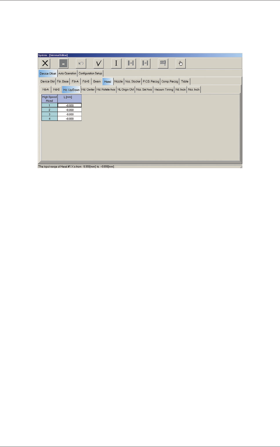
2.1.7 Head Up/Down Offset
When the "Head" tab is pressed in the "Device Offset" tab sheet and the "Hd
Up/Down" tab is selected, the following tab sheet appears.
Fig. 3F21 "Head Up/Down" Tab Sheet
Head 1, Head 2, Head 3, and Head 4
L (Height) [mm]
The set parameters are used to adjust the deviations (caused when the
master nozzle is attached to the head and lowered by the specifi ed
distance with the combined operations of the head and nozzle U/D axes)
based on the design value of the distance between the upper surface of
PCB and the lower surface of the nozzle. The amount of movement of
each axis is separately reviewed.
When the measured value is greater than the design one, a plus sign
must be affi xed to the offset data.
0607-003
2.1 Device Offset Data