3OM-1343-008_w.pdf - 第264页
6-33 AKFEDT -ID 2.1.14 Nozzle Inclination Offset When the "Head" tab is pressed in the "Device Offset" tab sheet and the "Noz. Incln" tab is selected, the following tab sheet appears. Fig. 3…
6-32
AKFEDT-ID
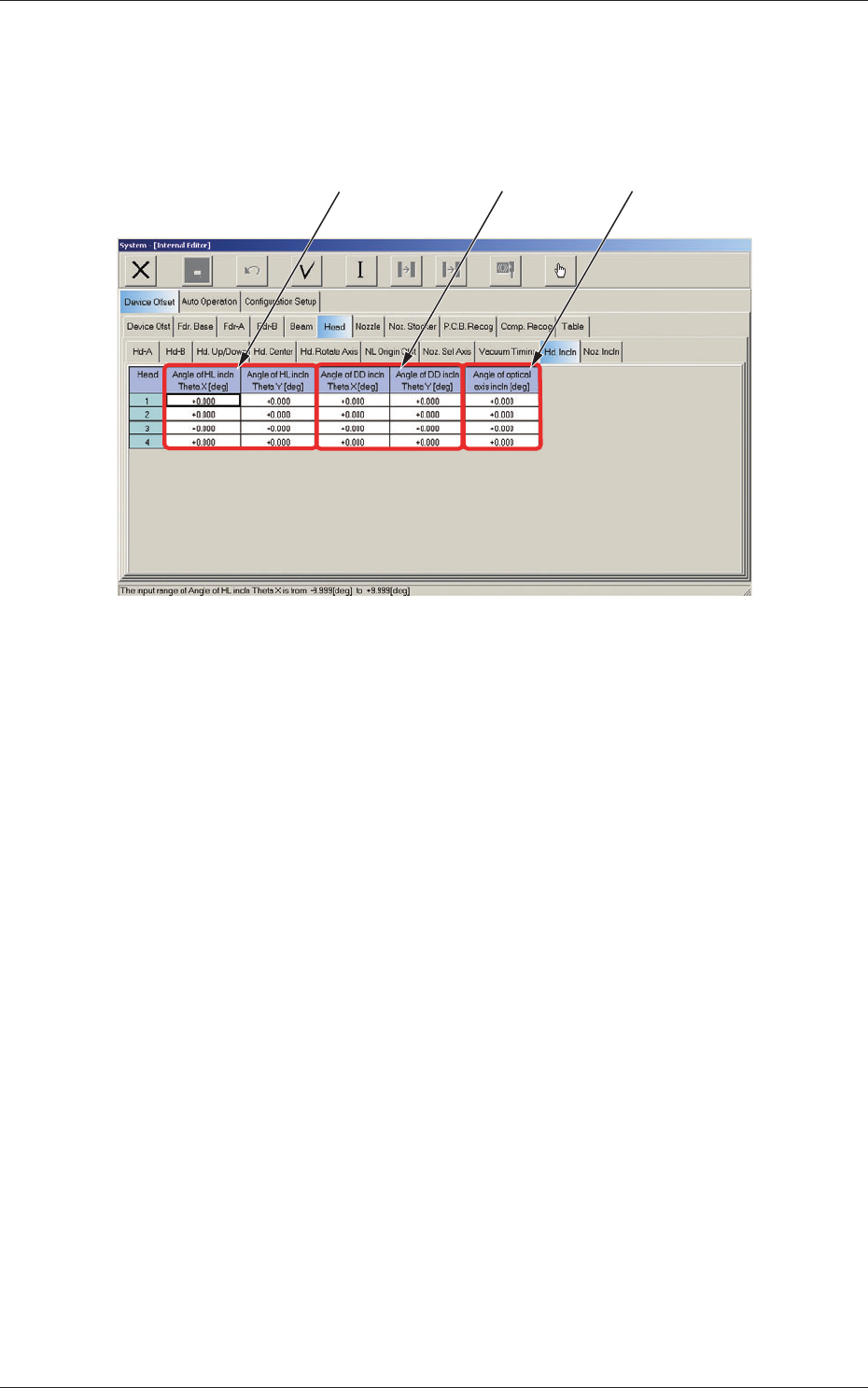
2.1.13 Head Inclination Offset
When the "Head" tab is pressed in the "Device Offset" tab sheet and the "Hd.
Incln" tab is selected, the following tab sheet appears.
[1] [2]
[3]
Fig. 3F30 "Head Incln" Tab Sheet
Head 1, Head 2, Head 3, and Head 4
[1] Angle of HL incln Theta X [deg], Theta Y [deg]
The set parameter is used to correct the deviations in the X and Y
direction that will be caused while the HL-axis is moving down if the
axis is tilted.
[2] Angle of DD incln Theta X [deg], Theta Y [deg]
The set parameter is used to correct the deviations in the X and Y
direction that will be caused while the HL-axis is moving down if the
DD-axis is tilted.
[3] Angle of optical axis incln [deg]
The set parameter is used to correct the angle of the component
recognition camera shot.
2.1 Device Offset Data
0607-003
6-33
AKFEDT-ID
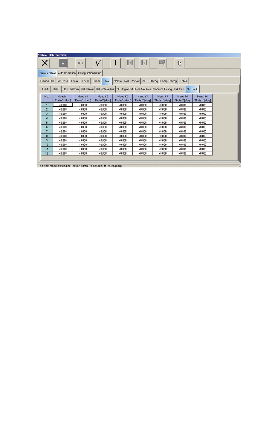
2.1.14 Nozzle Inclination Offset
When the "Head" tab is pressed in the "Device Offset" tab sheet and the
"Noz. Incln" tab is selected, the following tab sheet appears.
Fig. 3F31 "Noz. Incln" Tab Sheet
Nozzles 1 through 12
Head #1, Head #2, Head #3, and Head #4
Theta X [deg], Theta Y [deg]
These offsets are used to correct the deviations in the X and Y directions
that will be caused due to the inclination of the nozzle shaft while the
NL-axis is moving down.
2.1 Device Offset Data
0607-004

6-34
AKFEDT-ID
Intentionally Blank
2.1 Device Offset Data
0607-004