3OM-1343-008_w.pdf - 第277页
6-46 AKFEDT -ID Magni fi cation X (Horizontal) and Y (V ertical) [0.01 mm/pixel] Set how many micrometers should be equivalent to one pixel to specify the magni fi cation of the PEC recognition camera. The parameters are a…
6-45
AKFEDT-ID
Set the following offset values for each camera.
[1] PCB Recog Camera
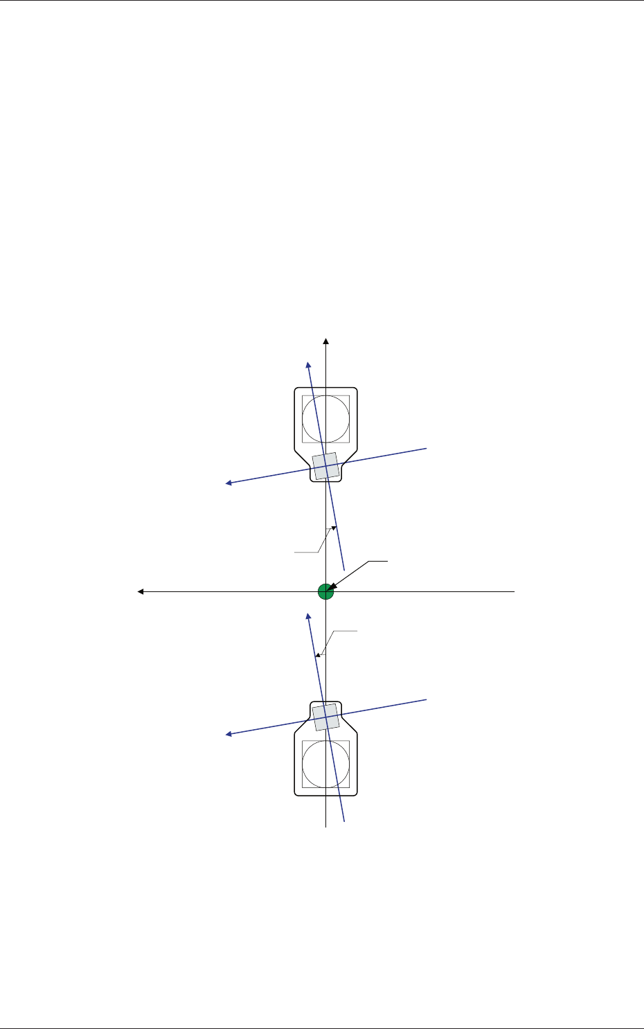
The set parameters are used to adjust the horizontal tilt of the PEC
recognition camera.
Z (Angle) [deg]
Set the parameters representing the angular deviations in the scanning
coordinates of the PEC recognition cameras based on the machine
reference X/Y coordinates (Xm-Ym).
When the camera scanning coordinates are shifted counterclockwise
to the machine reference X/Y coordinate system, a plus sign must be
affi xed to each offset data.
Xm(+)
Ym (+)
Yc (+)
Xc (+)
Yc (+)
Xc (+)
Xc-Yc : PEC Recognition
Coordinate System
Xm-Ym : Machine Reference
Coordinate System
Pm. Machine Reference
Coordinate Origin
Angle of PEC Recognition Camera
Angle of PEC Recognition Camera
Fig. 3F45
0601-002
2.1 Device Offset Data

6-46
AKFEDT-ID
Magnifi cation X (Horizontal) and Y (Vertical) [0.01 mm/pixel]
Set how many micrometers should be equivalent to one pixel to specify
the magnifi cation of the PEC recognition camera.
The parameters are automatically calculated through teaching
operations performed using the magnifi cation measurement jig.
•
Default:
2500
Contrast and Brightness
The brightness of the image captured by the PEC recognition camera
can be adjusted.
•
Defaults
Contrast :
102
Brightness :
128
Note
(a) The larger the value for "Contrast" is, the stronger the chromaticness
becomes.
(b) The larger the value for "Brightness" is, the brighter the whole view
becomes.
[2] PCB Recog Brightness
Coaxial Lighting, Ring Lighting
Set the brightness level for PEC recognition lighting.
•
Defaults
Coaxial Lighting :
30
Ring Lighting :
20
0601-002
2.1 Device Offset Data
6-47
AKFEDT-ID
0607-003
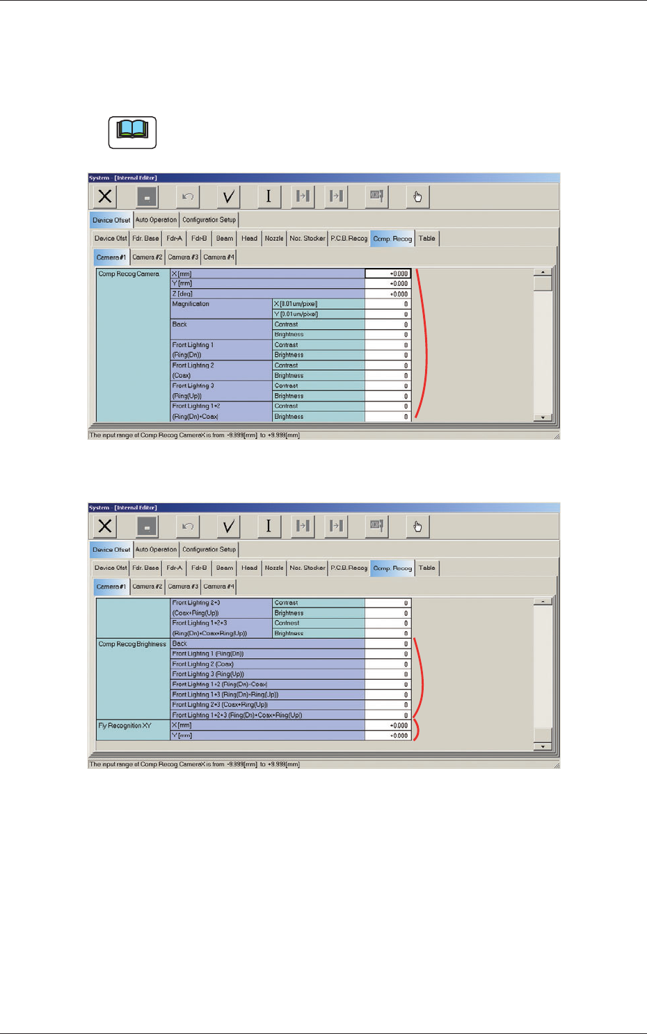
2.1.22 Component Recognition Offset
When the "Comp. Recog" tab is pressed in the "Device Offset" tab sheet and
the "Camera #1" tab is selected, the following tab sheet appears.
Note
As for the "Camera #2", "Camera #3", and "Camera #4" tab sheets, the
same contents as the "Camera #1" tab sheet are displayed.
[1]
Fig. 3F46 "Comp. Recog Camera #1" Tab Sheet (1)
[2]
[3]
Fig. 3F47 "Comp. Recog Camera #1" Tab Sheet (2)
2.1 Device Offset Data