3OM-1343-008_w.pdf - 第281页
6-50 AKFEDT -ID 0601-002 Contrast and Brightness The brightness of the image captured by the component recognition camera can be adjusted. • Default Contrast : 102 Brightness : 128 Note (a) The larger the value for "…
6-49
AKFEDT-ID
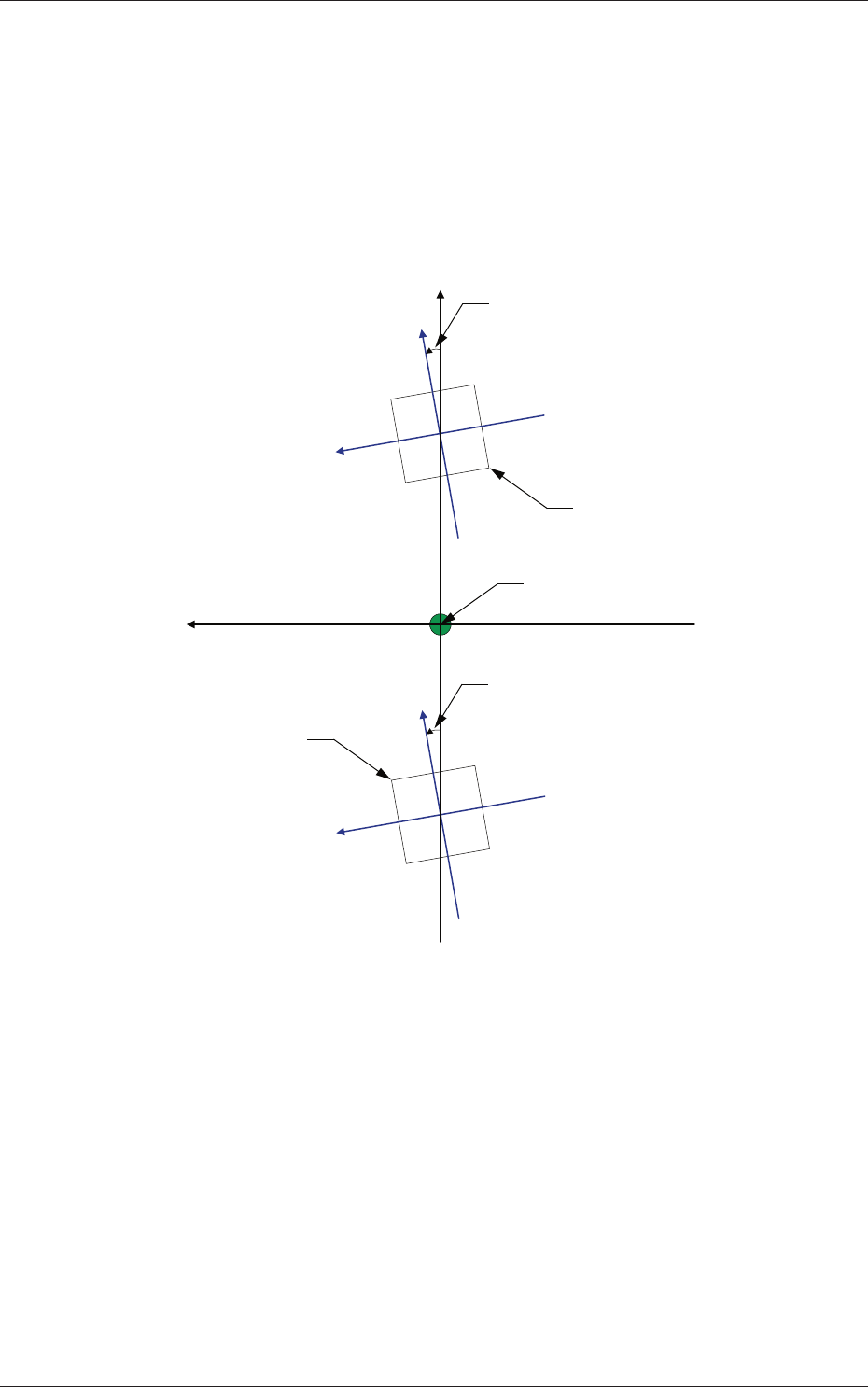
Z (Angle) [deg]
Set the parameters representing the angular deviations in the scanning
coordinates of the component recognition cameras based on the
machine reference X/Y coordinates (Xm-Ym).
When the camera scanning coordinates are shifted counterclockwise
to the machine reference X/Y coordinate system, a plus sign must be
affi xed to each offset data.
Xm(+)
Ym(+)
Xc-Yc : Component Recognition
Camera Coordinate System
Xc (+)
Yc (+)
Xc (+)
Yc (+)
Pm. Machine Reference
Coordinate Origin
Angle of Component Recognition Camera
Angle of Component Recognition Camera
Component Recognition Camera
Component Recognition
Camera
Xm-Ym : Machine Reference
Coordinate System
Fig. 3F49
Magnifi cation X (Horizontal) and Y (Vertical) [0.01 mm/pixel]
Set how many micrometers should be equivalent to one pixel to specify
the magnifi cation of the component recognition camera.
The parameters are automatically calculated through teaching
operations performed using the magnifi cation measurement jig.
•
Default:
6060
0601-002
2.1 Device Offset Data

6-50
AKFEDT-ID
0601-002
Contrast and Brightness
The brightness of the image captured by the component recognition
camera can be adjusted.
•
Default
Contrast
:
102
Brightness
: 128
Note
(a) The larger the value for "Contrast" is, the stronger the chromaticness
becomes.
(b) The larger the value for "Brightness" is, the brighter the whole view
becomes.
[2] Comp Recog Brightness
Back, Front Lighting 1 (Ring (Dn)), Front Lighting 2 (Coax), Front
Lighting 3 (Ring (Up)),
Front Lighting 1+2 (Ring (Dn)+Coax), Front Lighting 1+3 (Ring
(Dn)+Ring (Up)), Front Lighting 2+3 (Coax+Ring (Up)), Front
Lighting 1+2+3 (Ring (Dn)+Coax+Ring (Up))
Set the brightness level for component recognition lighting.
•
Default
Back : 128
Front Lighting 1 (Ring (Dn)) : 160
Front Lighting 2 (Coax) : 160
Front Lighting 3 (Ring (Up)) : 128
Front Lighting 1+2 (Ring (Dn)+Coax) : 160
Front Lighting 1+3 (Ring (Dn)+Ring (Up)) : 0
Front Lighting 2+3 (Coax+Ring (Up)) : 160
Front Lighting 1+2+3 (Ring (Dn)+Coax+Ring (Up)) : 0
[3] Fly Recognition XY
X (Horizontal) and Y (Vertical) [mm]
Obtain the defl ections (caused mainly due to the delay time of the
servoamplifi er and the strobe) of the images captured by the stopped
component recognition camera (still image capture) and the fl ying
component recognition camera (fl y image capture) and set the obtained
values to adjust the deviations in timing for image capture.
The set parameters are used to prevent a component from getting
affected by the delay and staying out of camera fi eld of view.
2.1 Device Offset Data
6-51
AKFEDT-ID
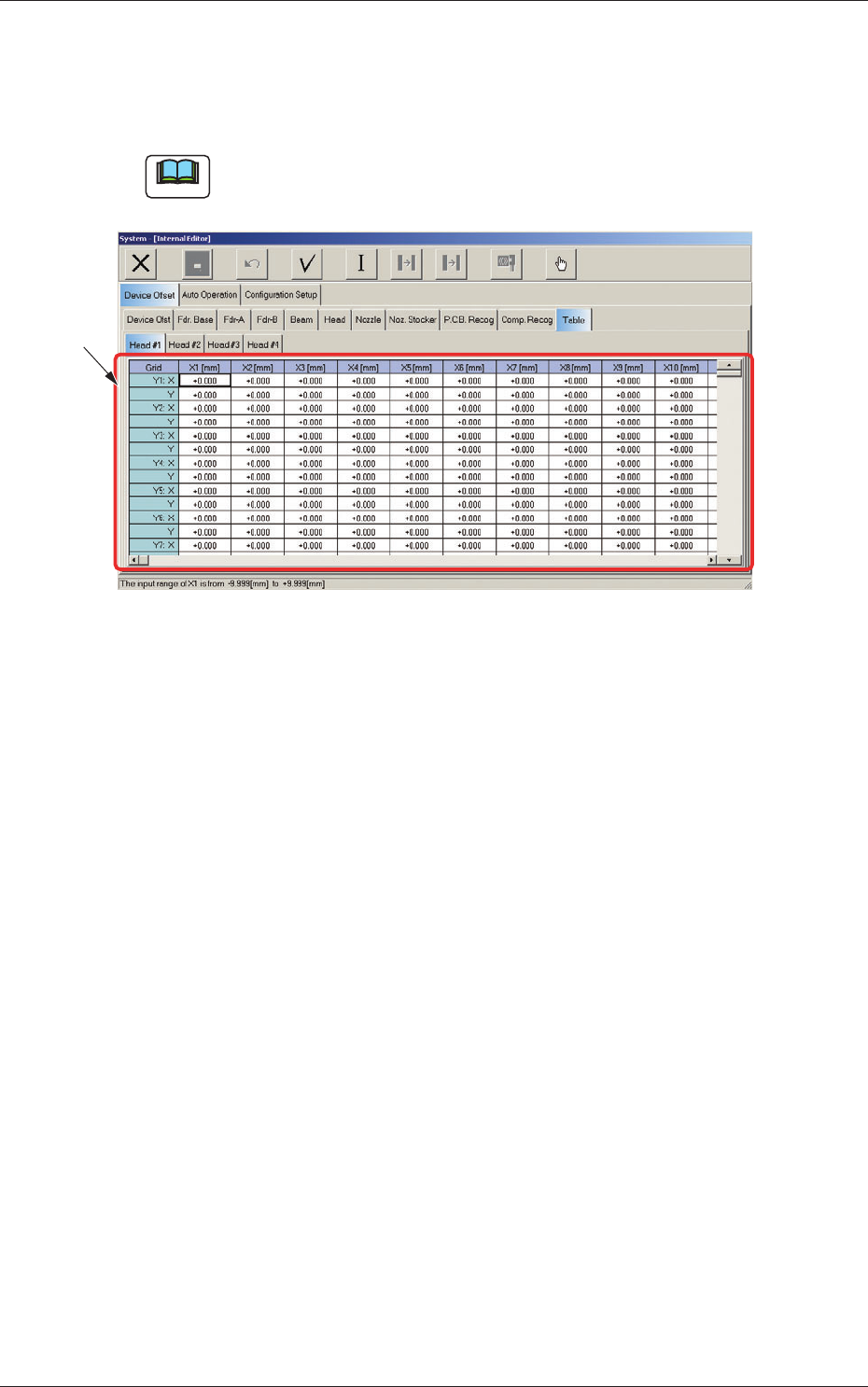
2.1.23 Table Offset
When the "Table" tab is pressed in the "Device Offset" tab sheet and the
"Head #1" tab is selected, the following tab sheet appears.
Note
As for the "Head #2", "Head #3", and "Head #4" tab sheets, the same
contents as the "Head #1" tab sheet are displayed.
[1]
Fig. 3F50 "Head #1" Tab Sheet
[1] Grid (X1 through X30, Y1 through Y30: X, Y) [mm]
Enter the amount of deviation based on the specifi ed distance when
Head #1 has moved as far as the specifi ed distance (each grid point,
X Direction: X1 through X30, Y Direction: Y1 through Y30) from the
PCB positioning reference.
These values are calculated automatically through the teaching
operation and entered in each text box.
0607-003
2.1 Device Offset Data