3OM-1343-008_w.pdf - 第310页
6-79 AKFEDT -ID Fdcl Mk Image Select one of the following options to specify how (bright or dark) the image of the nozzle end should be captured in the front lighting system. Dark Bright Fig. 3F70 Note The set parameter …
6-78
AKFEDT-ID
[Multi] Button
When selected, this button displays only the multifunctional nozzles.
Note
By pressing each title button in the nozzle data, the listed nozzles can be
re-arranged in the ascending or descending order (nozzle IDs, lengths,
etc.).
Nozzle ID
Shown are the nozzle IDs (names).
Shape Code
Set a nozzle shape in each text box. "Circle" or "Rect" can be selected.
Note
In the case of a rectangular nozzle, the pre-rotational pick-up control
(control based on the parameter set in the "Pickup angle [deg]" text box in
the "Component Library" edit window) may be required depending on the
packaged posture of a component.
Reference
Refer to the instruction manual of the component library for details.
Length [mm]
Set the nozzle length in this text box.
Tip Polarity
Set the polarity of the nozzle tip (shape).
Enable :
Special Nozzle with Polarity (Asymmetrical)
Disable :
Round Nozzle or the like without Polarity
Outline X (Horizontal) and Y (Vertical) [mm]
Set the outer dimensions of the nozzle tip section.
Note
In the case of "Circle", set the same dimensions for "X" and "Y".
In the case of "Rect", set Dimensions X and Y.
Outside Dimension X
Set the dimensions of the nozzle end.
Outside Dimension Y
Fig. 3F69
0604-003
3.2 Nozzle Data
6-79
AKFEDT-ID
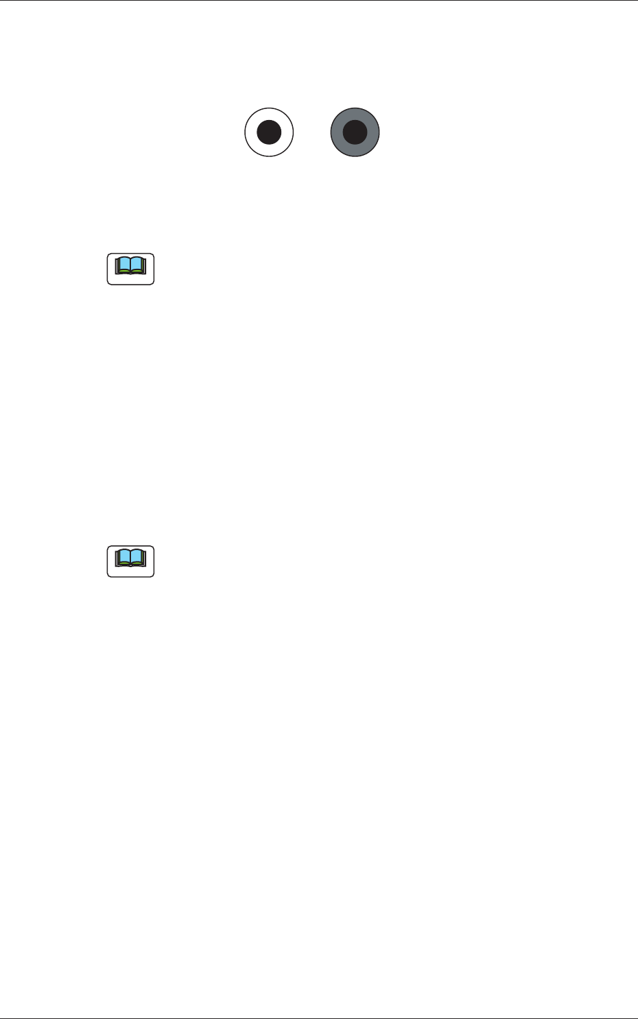
Fdcl Mk Image
Select one of the following options to specify how (bright or dark) the
image of the nozzle end should be captured in the front lighting system.
DarkBright
Fig. 3F70
Note
The set parameter is required for nozzle masking in the front lighting
system.
Lighting Method
Specify which lighting method can be used for each nozzle.
Select one of the following options.
Back-Lighting :
This function is available only in the back lighting
recognition system.
Front-Lighting :
This function is available only in the front lighting
recognition system.
Back/Front :
This function is available in both back and front
lighting recognition systems.
Note
"Front-Lighting" must be selected for such a nozzle that the image of the
area other than the nozzle tip appears dark in the back lighting system.
"Back-Lighting" must be selected for such a nozzle that the image of the
area other than the nozzle tip appears bright in the front lighting system.
0601-002
3.2 Nozzle Data
6-80
AKFEDT-ID
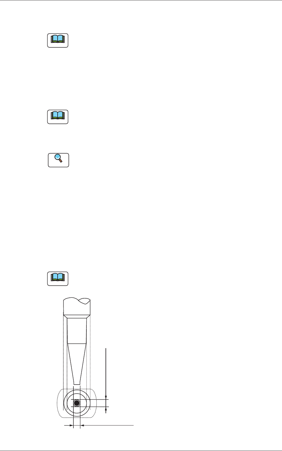
Nozzle Recog
1.0 mm
2.0 mm
Length
Diffusion
Plate
Reference Plane for
Nozzle Attachment
Height for
Recognition
Fig. 3F71
Lighting Method
Select one of the following options as a lighting method for the nozzle
recognition plane.
Back ltg, Fr ltg #1 (Ring Dn), Fr ltg #2 (Coax),
Fr ltg #3 (Ring Up)
Note
The following condition is required for recognition of a nozzle.
•
The nozzle height direction should be the one as depicted in the fi gure
below.
•
The object nozzle for recognition should be arranged in the camera
sensor.
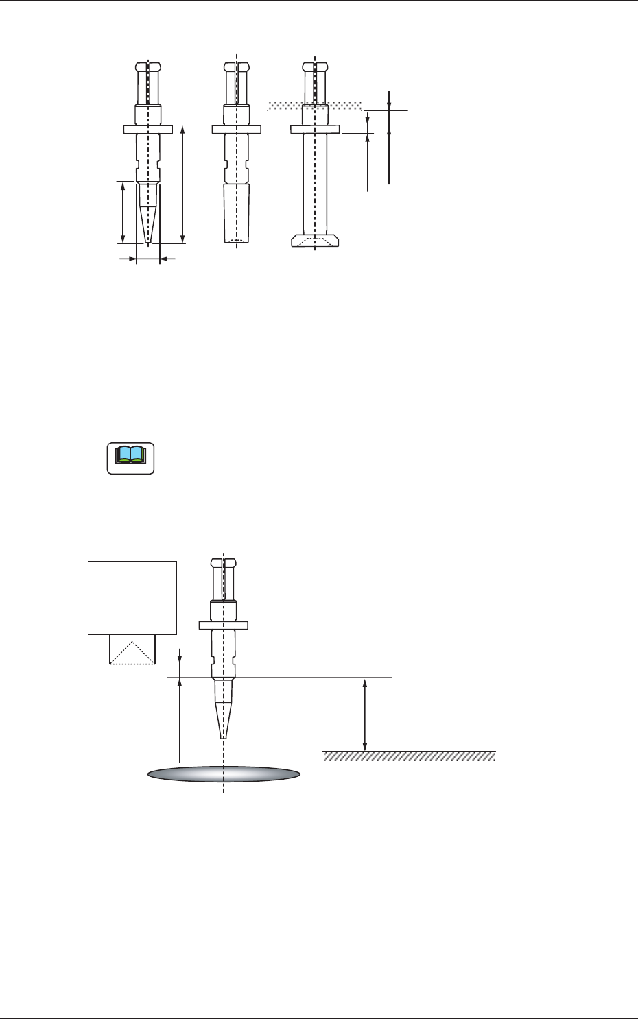
10.0 mm
PCB Surface
Linear
Measure
Sensor Light
Emitter
Component Recognition Camera Focus Position
1.0 mm or more
Camera Center
Fig. 3F72
Level [mm]
Set the height (level) of the nozzle recognition plane in comparison with the
nozzle end.
Outer Size [mm]
Set the outer diameter of the nozzle recognition plane.
0601-002
3.2 Nozzle Data