3OM-1343-008_w.pdf - 第92页
3-7 AKFEDT -ID (A01_05) Placement Reference Set the placement coordinate reference in this text box. The reference must be speci fi ed according to the input and output machines. Rear Left : The placement coordinate refer…
3-6
AKFEDT-ID
(A01_04)
PCB height offset [mm]
Set an offset value as a nozzle descending distance based on the upper
surface of the PCB in the component placement section.
This offset value applies to all components in the pattern program.
Normal Cases
Set
"
+0.000
"
(zero) in the text box.
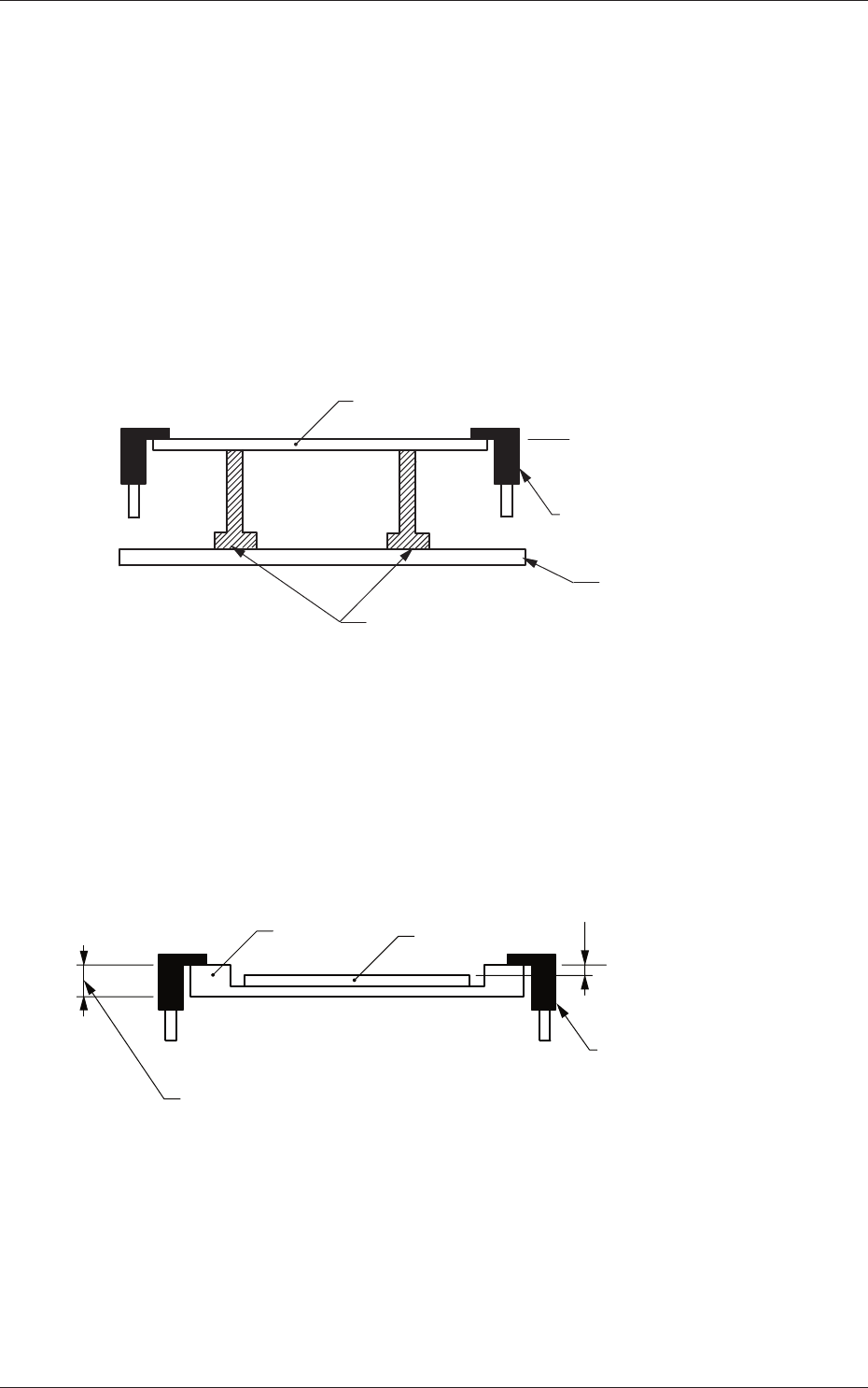
The fi gure below shows that the upper surface of a PCB is maintained
by the PCB support pins at the PCB upper surface reference.
PCB
PCB Upper Surface
Reference
Chute
Backup Pin
Backup Table
Fig. 3C6
Example of Jig PCB Usage
The fi gure below shows that the upper surface of a PCB is lower than
the PCB upper surface reference.
If
"
+ a
"
is set as an offset value at this time, components can be placed
correctly on the PCB.
a
T (Thickness)
Jig PCB
PCB
PCB Upper Surface
Reference
Chute
Fig. 3C7
0601-002
1.2 Operation Data
3-7
AKFEDT-ID
(A01_05)
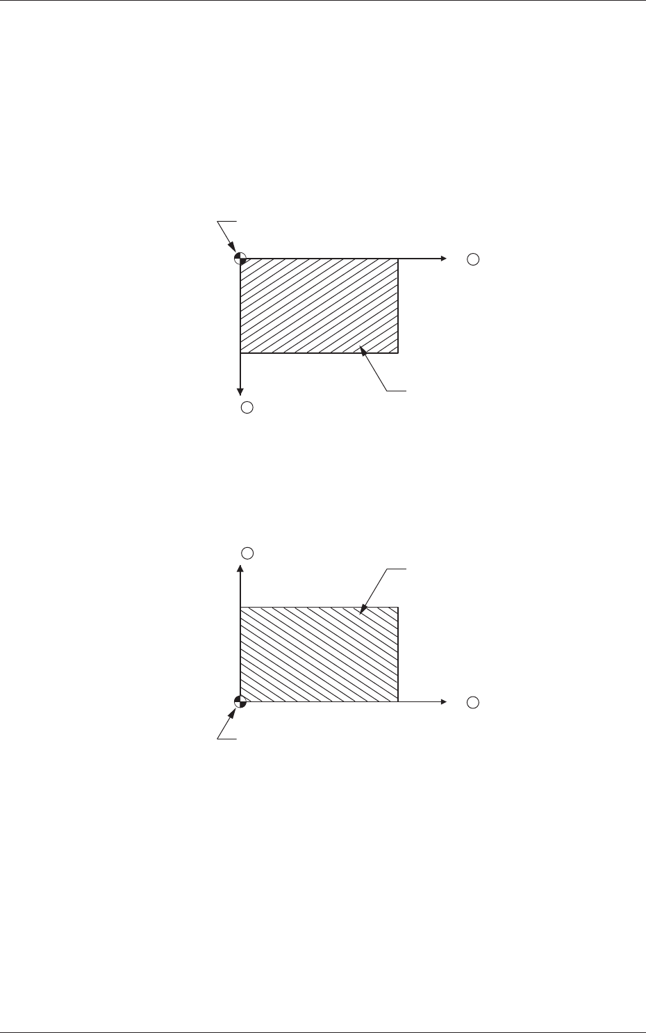
Placement Reference
Set the placement coordinate reference in this text box.
The reference must be specifi ed according to the input and output
machines.
Rear Left :
The placement coordinate reference is based on the
rear left side and specifi ed as follows.
Y
X
PCB
Placement Coordinate Reference (N
0)
+
+
Fig. 3C8
Front Left :
The placement coordinate reference is based on the
front left side and specifi ed as follows.
Y +
PCB
Placement Coordinate Reference (N
0)
X
+
Fig. 3C9
0601-002
1.2 Operation Data
3-8
AKFEDT-ID
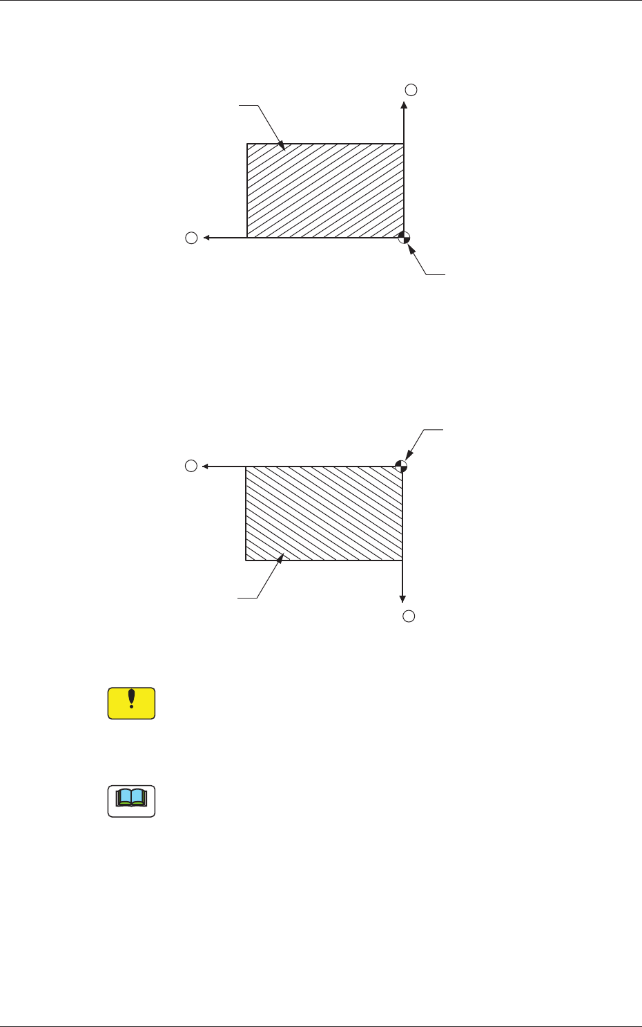
Front Right :
The placement coordinate reference is based on
the front right side and specifi ed as follows.
X +
Y +
PCB
Placement Coordinate
Reference (N
0)
Fig. 3C10
Rear Right :
The placement coordinate reference is based on
the rear right side and specifi ed as follows.
X
PCB
Placement Coordinate
Reference (N
0)
Y
+
+
Fig. 3C11
Notice
Be sure to set the same reference as the input and output
machines.
If a reference different from the input and output machines is
specifi ed, PCBs cannot be produced correctly.
Note
When a different reference is specifi ed in the pattern program and the
program is to be used for this machine, be sure to change the reference of
this machine to the different one.
0601-002
1.2 Operation Data