00197964-01_AI_Flex-Head-Options-Configuration_en - 第14页
Installing Flex Option 1 14 Assembly Instructions SIPLACE E Installation Procedures (Taking Location 2.1 as an Example) ► Place the he ight measure ment block FLEX LO C2 [03118 537-xx] onto the shim cov er and move head …
Installing Flex Option 1
Assembly Instructions SIPLACE E 13
2
2 Installing Flex Option 1
Installing Flex Option 1
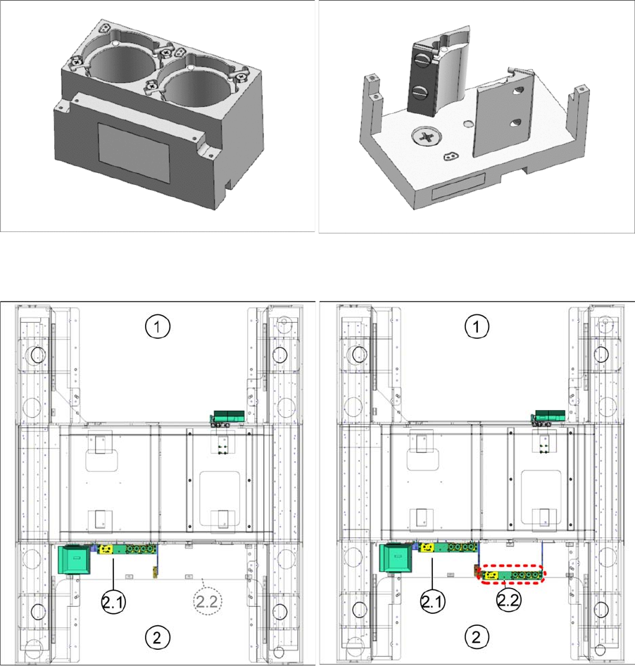
▪ A standard machine with NC FLEX std. cpl [03107775-xx] is equipped with one magazine holder with
two passive nozzle magazines of type [03103613-xx] and one passive nozzle magazine of type
[03109863-xx] at location 2.1.
▪ The large reject bin [03109719- xx] is located on the left at Location 2. The small reject bin
[03109739-xx] is located on the left at location 1.
Passive Nozzle Magazine Type (Quick Reference)
Standard Flex Flex Option 1
2x Magazine cpl. / 2 nozzles P&P / E-series
[03103613
-
xx]
1x Magazine cpl. / 1 nozzle P&P / E-series
[03109863
-
xx]
1 Location 1 2 Location 2
Flex Option 1 Configuration NC FLEX LOC 2.2 cpl. [03113126-xx] is located at the highlighted area.
It consists of a magazine holder with a flexible number of passive nozzle magazines ([03103613-xx] or
[03109863-xx]).
The order quantity depends on the customer's preference.
Installing Flex Option 1
14 Assembly Instructions SIPLACE E
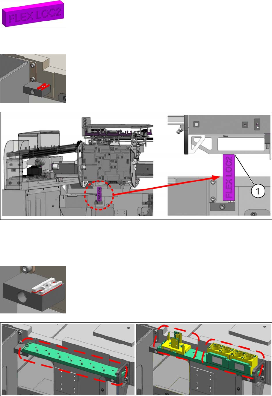
Installation Procedures (Taking Location 2.1 as an Example)
► Place the height measurement block FLEX LOC2 [03118537-xx] onto the shim cover and move head
holder manually towards the block with care.
► Check the gap with a feeler gauge (1).
► Determine the gap and the number of NC shims [03108395-xx] required.
Magazine holder single and double P+P magazine
► Place the magazine holder cpl./NC P+P/E-series [03103612-xx] onto the shim cover once the height
is adjusted.
► Secure it with four M5x20 cap screws at both ends.
► Height measurement block FLEX LOC2 [03118537-xx] is required to up
-
grade in the field.
► Mount the shim cover [03108393-xx] onto the mounting block Flex
[03106636-xx] at location 2.
► Mount the required shims underneath the shim cover and fasten them
with an M3x8 countersunk screw.
Installing Flex Option 1
Assembly Instructions SIPLACE E 15
► Assemble the necessary nozzle magazines as illustrated.
We recommend placing the single magazine [03109863-xx] on the left where the machine frame
shoulder clearance is located.
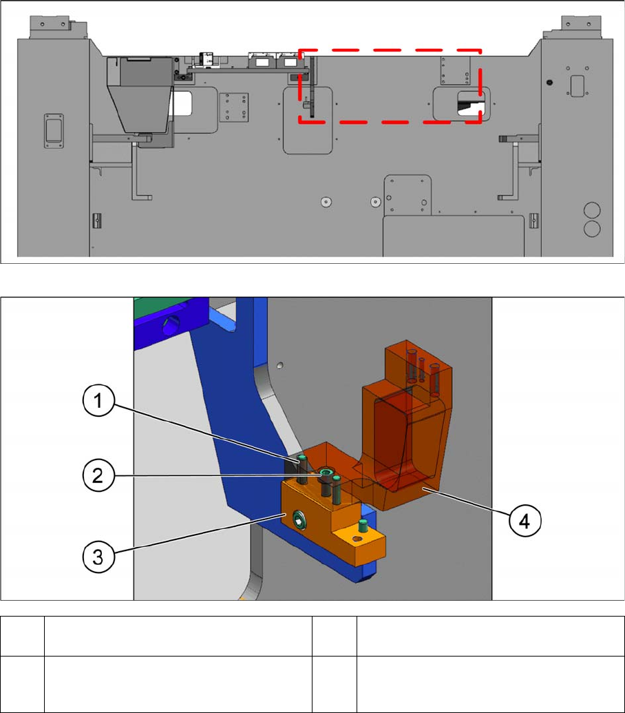
Installation at Location 2.2
Machine overview
► Place the mounting block (4) onto the 2 dowel pins (1) of the ETD, NC mounting left TWIN cpl. (3).
► Secure the mounting block (4) with 1 cap screw (2).
1 Ø4x20 dowel pins
(preinstalled in (3))
2 M4x16 cap screw
3 ETD, NC mounting left TWIN cpl.
[03113123
-
xx]
(standard FLEX machine configuration)
4 Mounting block left 2B [03112942
-
xx]