00197964-01_AI_Flex-Head-Options-Configuration_en - 第18页
Installing Flex Option 2 18 Assembly Instructions SIPLACE E Active Nozzle Magazine Types (Quick Reference) Installation Procedures ► Mount the nozzle station suppo rt [03105456-xx] onto the NC m oun ting bracket FLEX 1 L…
Installing Flex Option 2
Assembly Instructions SIPLACE E 17
3
3 Installing Flex Option 2
Installing Flex Option 2
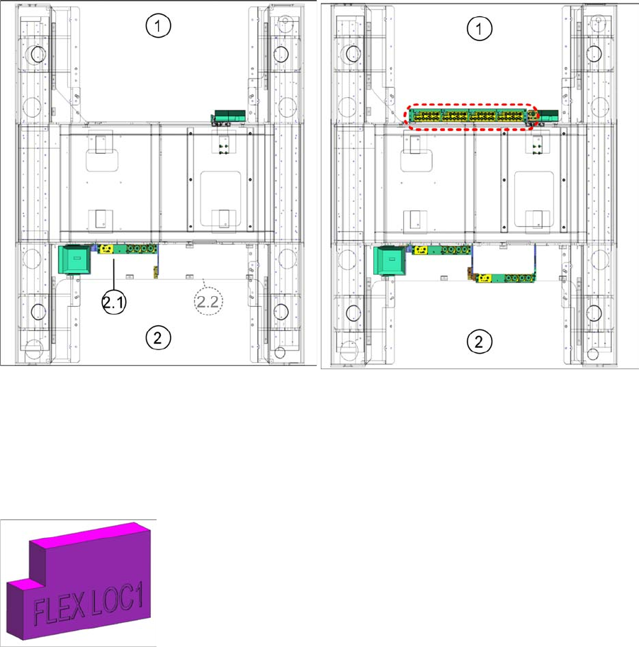
▪ A standard machine with NC FLEX std. cpl [03107775-xx] is equipped with one magazine holder with
two passive nozzle magazines of type [03103613-xx] and one passive nozzle magazine of type
[03109863-xx] at location 2.1.
Standard Flex Flex Option 2
1 Location 1 2 Location 2
The Flex Option 2 configuration NC FLEX LOC1 cpl. [03113131-xx] is located at the highlighted area.
It consists of a single row nozzle changer base plate [03106322-xx] with a flexible combination of active
nozzle magazines [03104048-xx], or [03105864-xx], or [03081446-xx] as shown above.
The order quantity depends on the customer's preference.
► The height measurement block FLEX LOC 1 [03118538-xx] is required to
upgrade in the field.
Installing Flex Option 2
18 Assembly Instructions SIPLACE E
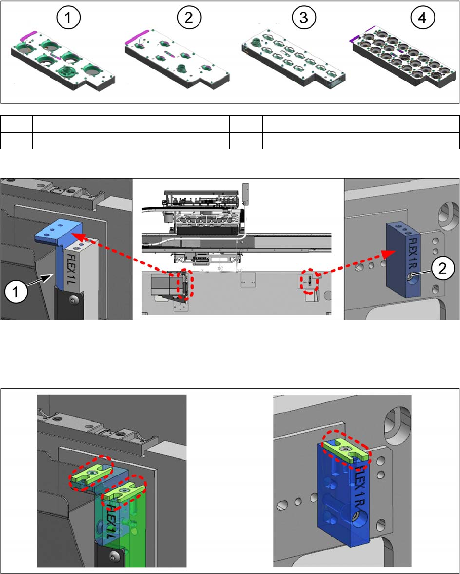
Active Nozzle Magazine Types (Quick Reference)
Installation Procedures
► Mount the nozzle station support [03105456-xx] onto the NC mounting bracket FLEX 1 Left
[03109945-xx] with two M4x10 countersunk screws (1) (screws not visible in the figure).
► Mount the NC mounting bracket FLEX 1 Right [03109942-xx] onto the machine base frame with one
M5x30 cap screw (2).
► Mount one shim cover each [03108393-xx] onto the nozzle station support [03105456-xx], the NC
mounting bracket FLEX 1 Left [03109945-xx], and the NC mounting bracket FLEX 1 Right
[03109942-xx].
1 Nozzle magazine type 38xx for RV6 2 Nozzle magazine type 39xx for RV6
3 Nozzle magazine type 30xx for RV12 4 Nozzle magazine type 40xx for CP14
Installing Flex Option 2
Assembly Instructions SIPLACE E 19
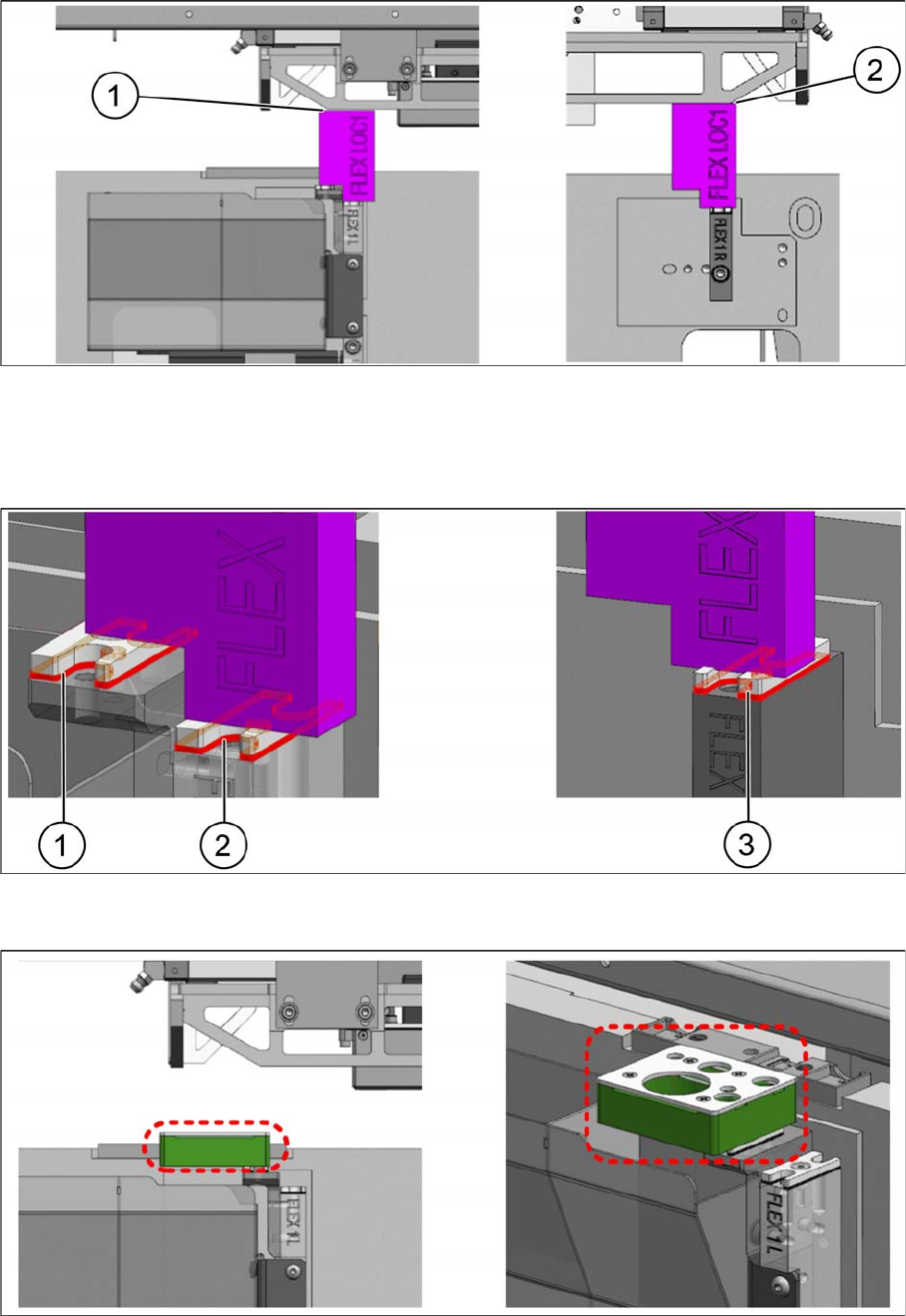
► Place the height measurement block FLEX LOC1 [03118538-xx] onto the shim covers of the mount
-
ing brackets and move the head holder manually towards the block with care.
► Check the gaps (1) and (2) with a feeler gauge.
► Determine the gap and the number of NC shims [03108395-xx] required.
► Place the required shims underneath the shim covers (1), (2), and (3) and fasten them with an M3x8
countersunk screw each.
► Place the reject device [03109608-xx] onto the shim cover (adjusted height).
► Secure it with two M4x20 countersunk screws.