00197964-01_AI_Flex-Head-Options-Configuration_en - 第20页
Installing Flex Option 2 20 Assembly Instructions SIPLACE E ► Remove the red c ove r shown an d locate t h e nozzle changer contro l ca ble [03102710-xx]. ► Connect the cable [03102710-xx] t o the cable of t he nozzle ch…
Installing Flex Option 2
Assembly Instructions SIPLACE E 19
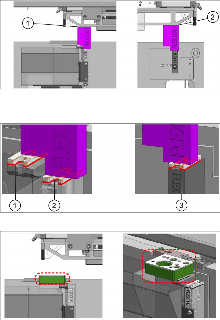
► Place the height measurement block FLEX LOC1 [03118538-xx] onto the shim covers of the mount
-
ing brackets and move the head holder manually towards the block with care.
► Check the gaps (1) and (2) with a feeler gauge.
► Determine the gap and the number of NC shims [03108395-xx] required.
► Place the required shims underneath the shim covers (1), (2), and (3) and fasten them with an M3x8
countersunk screw each.
► Place the reject device [03109608-xx] onto the shim cover (adjusted height).
► Secure it with two M4x20 countersunk screws.
Installing Flex Option 2
20 Assembly Instructions SIPLACE E
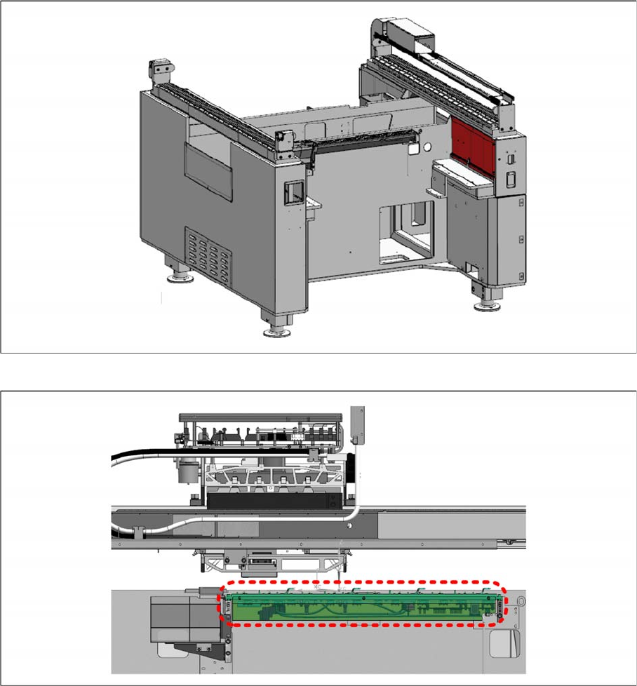
► Remove the red cover shown and locate the nozzle changer control cable [03102710-xx].
► Connect the cable [03102710-xx] to the cable of the nozzle changer NC single row [03106322
-
xx]
for SIPLACE CP6/CP12 (DLM 4), SIPLACE CP14 P.
► Mount the nozzle changer onto the shim covers on both ends and secure with four M5x14 cap
screws.
Installing Flex Option 2
Assembly Instructions SIPLACE E 21
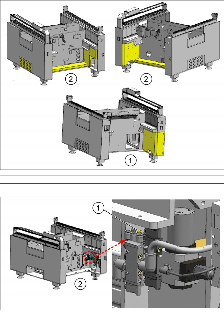
► On the machine, remove the yellow covers shown.
► Connect the Tube Nozzle Changer LOC1 tube [03102149-xx] (diameter 6 mm) to port 3 (1) of the air
service unit.
1 Location 1 2 Location 2
1 Port 3 2 Location 2