GWS 8-100角磨机说明书.pdf - 第10页
10 | English 1 609 92A 1 WG | (20.7.16) Bosch Power Tools Assembly Mounting the Protective Devices Before any work on the machine itself, pull the mains plug. Note: After breakag e of the g rinding disc during operatio…
English | 9
Bosch Power Tools 1 609 92A 1WG | (20.7.16)
Product Description and
Specifications
Read all safety warnings and all instruc-
tions. Failure to follow the warnings and in-
structions may result in electric shock, fire
and/or serious injury.
Intended Use
The machine is intended for cutting, roughing and brushing of
metal and stone materials without the use of water.
For cutting with bonded abrasives, a special cutting guard
(accessory) must be used.
When cutting in stone, provide for sufficient dust extraction.
With approved sanding tools, the machine can be used for
sanding with sanding discs.
Product Features
The numbering of the product features refers to the illustra-
tion of the machine on the graphics page.
1 Spindle lock button
2 On/Off switch
3 Lock-off button for On/Off switch
4 Combination spanner for M 10 grinder spindle
5 Auxiliary handle (insulated gripping surface)
6 Grinder spindle
7 Protection guard for grinding
8 Locking screw for protection guard
9 Mounting flange
10 Grinding wheel*
11 Clamping nut
12 Carbide grinding head*
13 Protection guard for cutting*
14 Cutting disc*
15 Hand guard*
16 Rubber sanding plate*
17 Sanding sheet*
18 Round nut*
19 Cup brush*
20 Cutting guide with dust extraction protection guard *
21 Diamond cutting disc*
22 Handle (insulated gripping surface)
*Accessories shown or described are not part of the standard de-
livery scope of the product. A complete overview of accessories
can be found in our accessories program.
Technical Data
Only for EC countries:
Noise/Vibration Information
Sound emission values determined according to
EN 60745-2-3.
Typically the A-weighted noise levels of the product are:
Sound pressure level 89 dB(A); Sound power level
100 dB(A). Uncertainty K =3 dB.
Wear hearing protection!
Vibration total values a
h
(triax vector sum) and uncertainty K
determined according to EN 60745-2-3:
Surface grinding: a
h
= 4.5 m/s
2
, K=1.5 m/s
2
,
Disk sanding: a
h
= 4.5 m/s
2
, K=1.5 m/s
2
.
The vibration level given in this information sheet has been
measured in accordance with a standardised test given in
EN 60745 and may be used to compare one tool with anoth-
er. It may be used for a preliminary assessment of exposure.
The declared vibration emission level represents the main ap-
plications of the tool. However if the tool is used for different
applications, with different accessories or insertion tools or is
poorly maintained, the vibration emission may differ. This
may significantly increase the exposure level over the total
working period.
An estimation of the level of exposure to vibration should also
take into account the times when the tool is switched off or
when it is running but not actually doing the job. This may signif-
icantly reduce the exposure level over the total working period.
Identify additional safety measures to protect the operator
from the effects of vibration such as: maintain the tool and the
accessories, keep the hands warm, organisation of work pat-
terns.
Angle Grinder GWS 8-100 Z GWS 8-115 Z
Article number
3 601 H31 5.. 3 601 H31 5..
Rated power input
W800800
Output power
W500500
Rated speed
min
-1
11000 11000
Grinding disc diameter, max.
mm 100 115
Thread of grinder spindle
M 10 M 14
Thread length (max.) of grinder spindle
mm 17 17
Weight according to EPTA-Procedure 01:2014
– with vibration-damping auxiliary handle
– with standard-auxiliary handle
kg
kg
2.0
1.9
2.0
1.9
Protection class
/II /II
The values given are valid for a nominal voltage [U] of 230 V. For different voltages and models for specific countries, these values can vary.
OBJ_BUCH-1556-005.book Page 9 Wednesday, July 20, 2016 11:23 AM
10 | English
1 609 92A 1WG | (20.7.16) Bosch Power Tools
Assembly
Mounting the Protective Devices
Before any work on the machine itself, pull the mains
plug.
Note: After breakage of the grinding disc during operation or
damage to the holding fixtures on the protection guard/power
tool, the machine must promptly be sent to an after-sales ser-
vice agent for maintenance. For addresses, see section “Af-
ter-sales Service and Application Service”.
Protection Guard for Grinding
Place the protection guard 7 on the
spindle collar. Adapt the position of
the protection guard 7 to the re-
quirements of the work step. Lock
protection guard 7 by tightening
locking screw 8 with combination
spanner 4.
Adjust the protection guard 7 in such a manner that
sparking is prevented in the direction of the operator.
Note: The encoding keys on the protection guard 7 ensure
that only a protection guard that fits the machine type can be
mounted.
Protection Guard for Cutting
For cutting with bonded abrasives, always use the pro-
tection guard for cutting 13.
Provide for sufficient dust extraction when cutting
stone.
The protection guard for cutting 13 is mounted in the same
manner as the protection guard for grinding 7.
Cutting Guide with Dust Extraction Protection Guard
The cutting guide with dust extraction protection guard 20 is
mounted in the same manner as the protection guard for
grinding 7.
Auxiliary Handle
Operate your machine only with the auxiliary handle 5.
Screw the auxiliary handle 5 on the right or left of the machine
head depending on the working method.
Hand Guard
For operations with the rubber sanding plate 16 or with
the cup brush/wheel brush/flap disc, always mount the
hand guard 15.
The hand guard 15 is fastened with the auxiliary handle 5.
Mounting the Grinding Tools
Before any work on the machine itself, pull the mains
plug.
Do not touch grinding and cutting discs before they
have cooled down. The discs can become very hot while
working.
Clean the grinder spindle 6 and all parts to be mounted.
For clamping and loosening the grinding tools, lock the grind-
er spindle with the spindle lock button 1.
Actuate the spindle lock button only when the grinder
spindle is at a standstill. Otherwise, the machine may be-
come damaged.
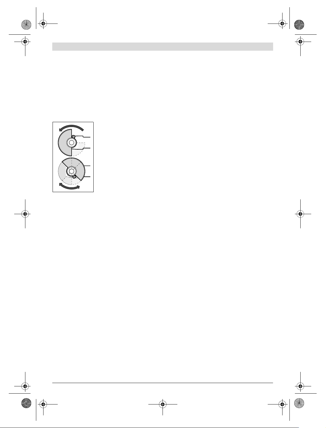
Grinding/Cutting Disc
Pay attention to the dimensions of the grinding tools. The
mounting hole diameter must fit the mounting flange without
play. Do not use reducers or adapters.
When using diamond cutting discs, pay attention that the di-
rection-of-rotation arrow on the diamond cutting disc and the
direction of rotation of the machine (see direction-of-rotation
arrow on the machine head) agree.
See graphics page for the mounting sequence.
To fasten the grinding/cutting disc, screw on the clamping nut
11 and tighten it with the combination spanner 4.
After mounting the grinding tool and before switching
on, check that the grinding tool is correctly mounted
and that it can turn freely. Make sure that the grinding
tool does not graze against the protection guard or oth-
er parts.
Flap Disc
For operations with the flap disc, always mount the
hand guard 15.
Rubber Sanding Plate
For operations with the rubber sanding plate 16, al-
ways mount the hand guard 15.
See graphics page for the mounting sequence.
Screw on round nut 18 and tighten it with the combination
spanner 4.
Cup Brush/Disc Brush
For operations with the cup brush/wheel brush, always
mount the hand guard 15.
See graphics page for the mounting sequence.
The cup brush/disc brush must be able to be screwed onto
the grinder spindle until it rests firmly against the grinder
spindle flange at the end of the grinder spindle threads. Tight-
en the cup brush/disc brush with an open-end spanner.
Approved Grinding Tools
All grinding tools mentioned in these operating instructions
can be used.
The permissible speed [min
-1
] or the circumferential speed
[m/s] of the grinding tools used must at least match the values
given in the table.
Therefore, observe the permissible rotational/circumferen-
tial speed on the label of the grinding tool.
OBJ_BUCH-1556-005.book Page 10 Wednesday, July 20, 2016 11:23 AM
English | 11
Bosch Power Tools 1 609 92A 1WG | (20.7.16)
Rotating the Machine Head
Before any work on the machine itself, pull the mains
plug.
The machine head can be
rotated with respect to
the machine housing in
90° steps. In this man-
ner, the On/Off switch
can be brought into a
more convenient posi-
tion for special working
situations, e. g., for cut-
ting operations using the
cutting guide with dust
extraction protection
guard 20 or for left-hand-
ed persons.
Completely unscrew the four screws. Rotate the machine
head carefully, without removing it from the housing, to the
new position. Screw in and tighten the four screws again.
Dust/Chip Extraction
Dust from materials such as lead-containing coatings,
some wood types, minerals and metal can be harmful to
one’s health. Touching or breathing-in the dust can cause
allergic reactions and/or lead to respiratory infections of
the user or bystanders.
Certain dust, such as oak or beech dust, is considered car-
cinogenic, especially in connection with wood-treatment
additives (chromate, wood preservative). Materials con-
taining asbestos may only be worked by specialists.
– As far as possible, use a dust extraction system suitable
for the material.
– Provide for good ventilation of the working place.
– It is recommended to wear a P2 filter-class respirator.
Observe the relevant regulations in your country for the
materials to be worked.
Prevent dust accumulation at the workplace. Dust can
easily ignite.
Operation
Starting Operation
Observe correct mains voltage! The voltage of the pow-
er source must agree with the voltage specified on the
nameplate of the machine. Power tools marked with
230 V can also be operated with 220 V.
Hold power tool by insulated gripping surfaces 22 and
auxiliary handle 5 only. The accessory may contact hid-
den wiring or its own cord. Accessory contacting a “live”
wire may make exposed metal parts of the power tool “live”
and shock the operator.
When operating the machine with power from mobile genera-
tors that do not have sufficient reserve capacity or are not
equipped with suitable voltage control with starting current
amplification, loss of performance or untypical behavior can
occur upon switching on.
Please observe the suitability of the power generator being
used, particularly with regard to the mains voltage and fre-
quency.
Switching On and Off
To start the machine, first slide the lock-off button 3 to the
rear and then push the On/Off switch 2 and keep it pressed.
To switch off the machine, release the On/Off switch 2.
Check grinding tools before using. The grinding tool
must be mounted properly and be able to move freely.
Carry out a test run for at least one minute with no load.
Do not use damaged, out-of-centre or vibrating grind-
ing tools. Damaged grinding tools can burst and cause in-
juries.
Working Advice
Before any work on the machine itself, pull the mains
plug.
Exercise caution when cutting slots in structural walls;
see Section “Information on Structures”.
Clamp the workpiece if it does not remain stationary
due to its own weight.
Do not strain the machine so heavily that it comes to a
standstill.
After heavily straining the power tool, continue to run
it at no-load for several minutes to cool down the acces-
sory.
Do not touch grinding and cutting discs before they
have cooled down. The discs can become very hot while
working.
Do not use the power tool with a cut-off stand.
Rough Grinding
Never use a cutting disc for roughing.
The best roughing results are achieved when setting the ma-
chine at an angle of 30° to 40°. Move the machine back and
forth with moderate pressure. In this manner, the workpiece
will not become too hot, does not discolour and no grooves
are formed.
max.
[mm]
[mm]
D b d [min
-1
] [m/s]
100
115
6
6
16
22
11000
11000
80
80
100
115
–
–
–
–
11000
11000
80
80
70
70
30
30
M10
M14
11000
11000
45
45
b
d
D
D
D
b
d
OBJ_BUCH-1556-005.book Page 11 Wednesday, July 20, 2016 11:23 AM