Vista Machine Overview.pdf - 第13页
MACHI NE O VERVIEW MACHINE PRINT CY CLE Chapter Issue 1 Sep 02 Technical Reference Manual 3.13 MACHINE PRINT CYCLE The followin g is a typical machine print cycle with camera mounted bord stop, described for step mode: 1…
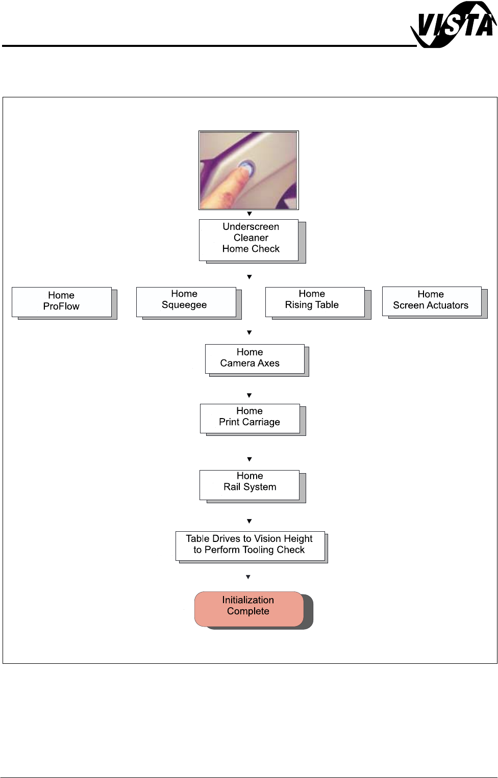
MACHINE OVERVIEW
MACHINE INITIALIZATION
3.12 Technical Reference Manual Chapter Issue 1 Sep 02
MACHINE INITIALIZATION

MACHINE OVERVIEW
MACHINE PRINT CYCLE
Chapter Issue 1 Sep 02 Technical Reference Manual 3.13
MACHINE PRINT CYCLE
The following is a typical machine print cycle with camera mounted bord stop,
described for step mode:
1. Run is pressed on the MMI and the table carries out a rail lifted check.
2. The camera positions itself at the board stop co-ordinates.
3. The board stop lowers into position ready for the incoming board.
4. The print carriage moves to the start of the print stroke and both squeegees
drive to their dwell height (25mm above the stencil).
5. Auto Board is pressed and the board is transported into the machine
stopping at the board stop.
6. The belts stop running as soon as the board stop sensor detects the board.
7. The board clamp mechanism operates and the board stop retracts.
8. The camera carriage drives to the position determined by Fiducial 1 X & Y
co-ordinates.
9. The chase clamps come on.
10.The rising table carries out a rail lift check then drives up to vision height.
11. The vision data window displays the board fiducial on the left and the stencil
fiducial on the right of the split display.
12.The fiducials are located and a small cross appearing in the centre of each
fiducial on the split display indicates successful location.
13.While the camera drives to Fiducial 2 X and Y coordinates, the location of
the fiducial 1 board and stencil fiducials are copied to the align data
structure.
14.The Fiducial 2 board and stencil fiducials are located.
15.The camera carriage drives to its home position while copying location data
for Fiducial 2 to the align data structure.
16.The rising table moves up to the print height minus 3mm and the squeegee
moves to 0.5mm - 1mm above the surface of the stencil.
17.The rising table drives up to the print height.
18.If the stencil requires correction the chase clamps are turned off and
realignment occurs. When aligned and checked the chase clamps come on
again.
19.Either the front or rear squeegee drives down to the calculated pressure
setting as set in the board parameter menu. If the actual pressure differs
from the set pressure by more than +/- 1Kg a squeegee pressure error
window is displayed. The user is given the option to abort the print or
continue the print.
20.If continue is selected, the print carriage drives at the set speed in the board
parameter menu.
21.On completion of the print stroke the average squeegee pressure is calcu-
lated and if it differs from the set pressure by more than +/- 1Kg a squeegee
pressure error window is displayed. The user is given the option to abort or
continue.
22.If continue is selected, a new squeegee displacement is calculated for the

MACHINE OVERVIEW
MACHINE PRINT CYCLE
3.14 Technical Reference Manual Chapter Issue 1 Sep 02
next print cycle on the particular squeegee.
23.The squeegee mechanism releases full pressure but keeps the squeegee
in contact with the stencil with 0.5kg force.
24.The board count is incremented.
25.The chase clamps are de-energized and the rising table drives down as set
by the separation speed in the board parameter menu until it is clear of the
stencil by the separation distance, at the same time the printing squeegee
drives down to dwell height.
26.The rising table drives down to a height dependent on the under board
clearance setting, at full speed and de-energizes the board clamps.
27.The front and rear belts drive until the board is detected at the output sensor.
28.The cycle count for the screen cleaner is incremented and if the value has
reached the values set by the clean screen rate then the appropriate cycle
is performed.