Dek-265GSX-User-Manual.pdf.pdf - 第104页
STAGE 9 2Di Setup For a complete explanation of 2Di and its setup refer to the 2D Inspection Chapter. 1.88 User Manual Software Version 6 MACHINE PROGRAMMING STAGE 9
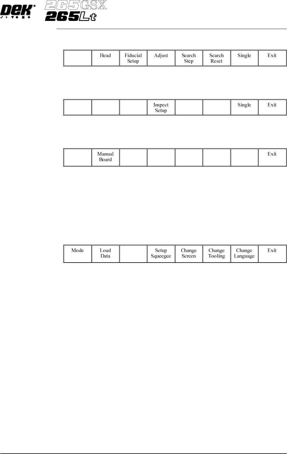
9.
Select Step (F1).
Step
10.
Select Step (F1).
Step
11.
Select Auto Board (F1).
Auto
Board
12. Remove the board from the conveyor and inspect the print for alignment. If
the alignment is satisactory go to Step 16, if the alignment needs adjusting,
calculate the following:
X Offset, Y Offset and θ Offset.
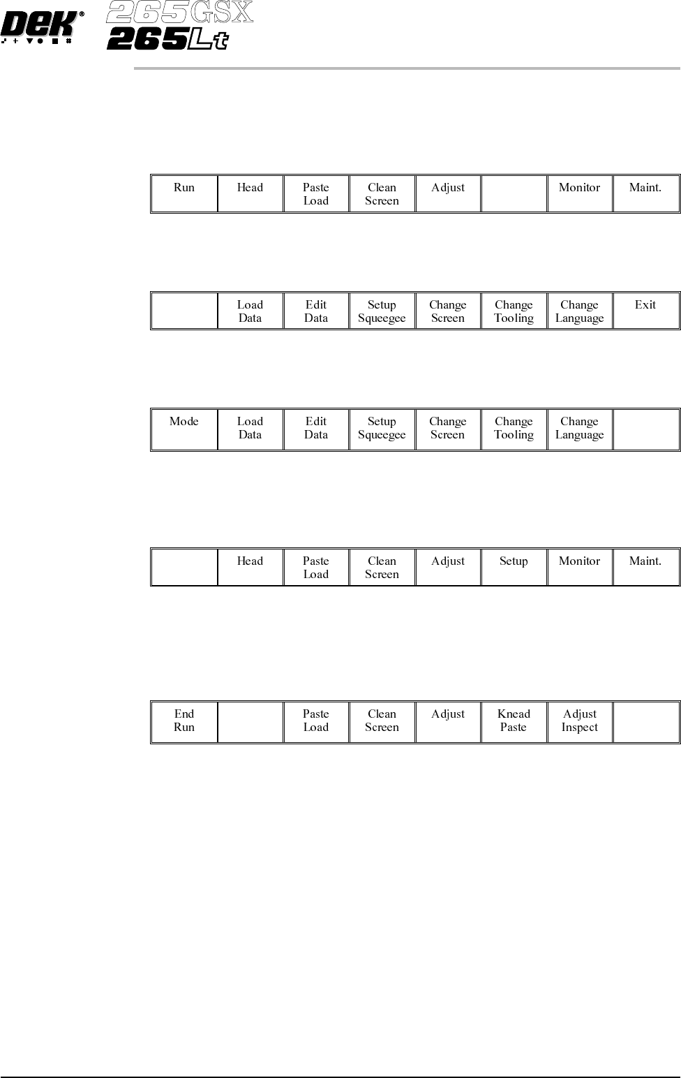
13.
Select Edit Data (F3).
Edit
Data
14.
Enter the X Offset, Y Offset and θ Offset, calculated in Step 12 to both the
Forward and Reverse set of offsets.
15. Repeat Steps1-12until the alignment is correct for both a forward and
reverse print.
16. If 2D Inspection is being used continue with Stage 9, if 2D Inspection isn’t
being used go to Stage 10.
Software Version 6 User Manual 1.87
MACHINE PROGRAMMING
STAGE 8

STAGE 9
2Di Setup For a complete explanation of 2Di and its setup refer to the 2D Inspection
Chapter.
1.88 User Manual Software Version 6
MACHINE PROGRAMMING
STAGE 9
STAGE 10
Running a Product in Run Mode
1.
Select Setup (F6)
Setup
2.
Select Mode (F1) until Auto is indicated in the mode option on the screen.
Mode
3.
Select Exit (F8).
Exit
4.
Select Run (F1). If squeegees are being used continue with Step 5, if
ProFlow is being used go to Step 19.
Run
5. During the first print stroke, when the squeegee is down printing on the
board, select Stop Cycle (F2). The print cycle stops and the printer lid bolt
releases allowing access to the print carriage.
Stop
Cycle
6. Lift the front printhead cover.
7. Release the screws holding one paste deflector allowing it to drop into
contact with the screen.
Software Version 6 User Manual 1.89
MACHINE PROGRAMMING
STAGE 10