Dek-265GSX-User-Manual.pdf.pdf - 第159页
2. Type vortoff using the keyboard. 3. Press Enter , the message ‘Vortex Under-Screen Cleaner Disabled’ is displayed in the message prompt bar. The silver under screen cleaner becomes the current cleaner and all cleaner …
The value of the configuration parameter cleaner type is set to silver and this
parameter is written to the configuration file.
4.
Press Exit.
To enable the Vortex under screen cleaner carry out the following:
1.
Press the function key F10 on the keyboard, a window of the following form
is displayed:
2.
Type vorton using the keyboard.
3.
Press Enter, the message ‘Vortex Under-Screen Cleaner Enabled’ is
displayed in the message prompt bar.
The Vortex under screen cleaner becomes the current cleaner and all cleaner
parameters become appropriate to the Vortex cleaner.
The value of the configuration parameter cleaner type is set to Vortex and
this parameter is written to the configuration file.
4.
Press Exit.
To disable the Vortex under screen cleaner carry out the following:
1.
Press the function key F10 on the keyboard, a window of the following form
is displayed:
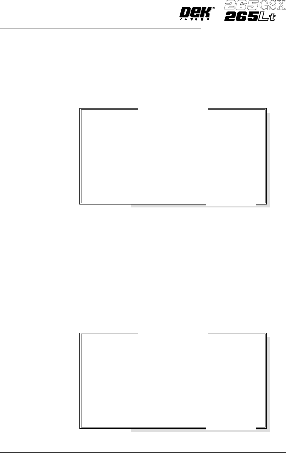
2.24 User Manual Software Version 6
SET PREFERENCES
PREFERENCES
Enter to Close ...
Serial Number
Processor Type
Executable date
Executable time
Executable name
Software Version
Options Enabled
Comms Driver
DOS Memory
Free DOS Memory
Available RAM
:
:
:
:
:
:
:
:
:
:
:
201305
486DX - or higher
April 19 1999
10:57:38
RR0400.EXE
04.00
SBNG
TCP
512 kb
316 kb
3223 kb
DEK 265 GS
(
X
)

2.
Type vortoff using the keyboard.
3.
Press Enter, the message ‘Vortex Under-Screen Cleaner Disabled’ is
displayed in the message prompt bar.
The silver under screen cleaner becomes the current cleaner and all cleaner
parameters revert to being appropriate to the previous cleaner.
The value of the configuration parameter cleaner type is set to silver and this
parameter is written to the configuration file.
4.
Press Exit.
Paste Trails Provides the capability to reduce solder paste trails from squeegees
automatically, options are:
Disabled; Mode 1
Ifmode1 is selected, any paste that has dripped from the squeegeeis scooped up,
by the squeegee back to the paste roll. This process occurs at the start of every
stroke, with the print mode set to print/print and at the start of only the print
stroke, when the print mode is set to flood/print orprint/flood.
Transport Wait
Mode
This option enables the product to be held in contact with the screen until both
upline and downline systems are ready to transfer, options are:
Standard; Hold_at_Print
The default is Standard.
Clamp Type Sets the type of board clamp used, options are:
Board Clamp; Snuggers
The default is Board Clamp.
To eliminate vacuum seal loss during alignment, if the Snuggers option is
selected and the tooling type is Vacuum, the rails do not dip when the camera is
traversing.
Snugger Thickness This Set Preference appears if Snuggers has been selected from the Clamp Type
preference
Min 0.8mm
Max2.0mm (2.01mm is displayed but 2.0mm is the maximumvalueselectable)
Increments 0.1mm
The default is 1.6mm.
Tooling Monitoring This parameter sets, while Feature Licensing asserts that use of Tooling
Deviation Monitoring is authorized, the frequency (in boards printed) at which
monitoring is performed. Monitoring is also carried out on the first print stroke
of a print run.
Min 0 boards (Tooling Monitoring disabled)
Max 200 boards
Increments 1
Software Version 6 User Manual 2.25
SET PREFERENCES
PREFERENCES
The default is 0 boards.
This feature only applies while squeegees are fitted.
When a particular print stroke is being monitored, as the squeegee traverses the
image the pressure being applied is measured and recorded. Any variations in
the load being applied, as a result of insufficient tooling support or underside
components coming intocontact with thetooling are noted. Upon completion of
the print stroke, the deviation in the pressure applied over the print stroke is
determined and expressed as the tooling deviation. The tooling deviation is
calculated from the minimum and maximum values and expressed as a
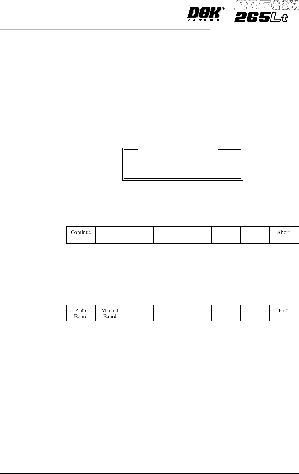
percentage. If the tooling deviation exceeds the permitted threshold, as set by
the Tooling Deviation parameter in the product file, a cyclic log text file called
deviate.dat is written and the following window is displayed:
NOTE
The number of samples is the amount of pressure variations recorded during the
print stroke.
The following menu bar is displayed:
On selecting Continue printing proceeds until it is interrupted by some other
cause.
On selecting Abort printing is discontinued and the following menu bar is
displayed, to enable the board to be removed from the machine:
If the number of samples (pressure variations) during a print stroke is less than 2
or the minimum value is zero, the error message ‘Failed to determine Tooling
Deviation’ is displayed.
Display Type Sets the type of status page displayed on the monitor, options are:
Type 1; Type 2
The default is Type 1.
Fiducial Monitoring The parameter enables and disables the intelligent fiducial monitoring feature,
options are:
Smart; Normal
The default is Smart.
2.26 User Manual Software Version 6
SET PREFERENCES
PREFERENCES
Excessive Tooling Deviation
Tooling Deviation : 25.08 %
Number of Samples : 81
Check the Board Support.