Dek-265GSX-User-Manual.pdf.pdf - 第276页
8.12 User Manual Software Version 6 2Di INSPECTION MODULE OVERVIEW Adjust Lighting: Adjust so all boar d pads are white with sharp edges and the scr een is seen clearly . Add Limits Sets: Set wide toler ances so no alarm…
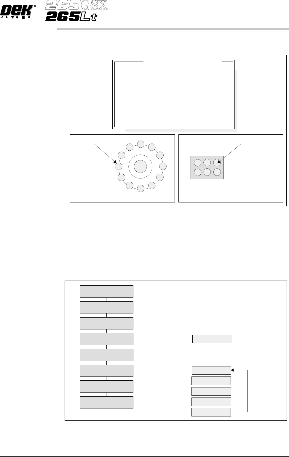
For the green camera the lighting parameters and their functions are shown
below.
Inspection Setup Correct inspection setup is the key to effective inspection. By following the
steps of the setup sequence, shown in the summary below and the setup guide
over the page, effective inspection may be achieved.
Software Version 6 User Manual 8.11
2Di INSPECTION
MODULE OVERVIEW
8
8
8
8
-1.0
-1.5
2.0
2.0
Inspection Lighting Parameters
Screen Vertical
Screen Oblique
Board Vertical
Board Oblique
Window Left
Window Top
Window Width
Window Height
Oblique Lighting LED
Board and Screen Oblique Lighting
Direct Lighting LED
Board and Screen Direct Lighting
Figure 8-11 Software Controlled Lighting - Green Camera
Setup
Set Preferences
Edit Data
Load Product File
Inspect Setup
Edit Global
Edit Limits
Run
Inspect
Edit Site
Limit Options
Add Site
Learn Site
Learn Board
Auto Learn
Light Setup
Figure 8-12 Summary of Setup
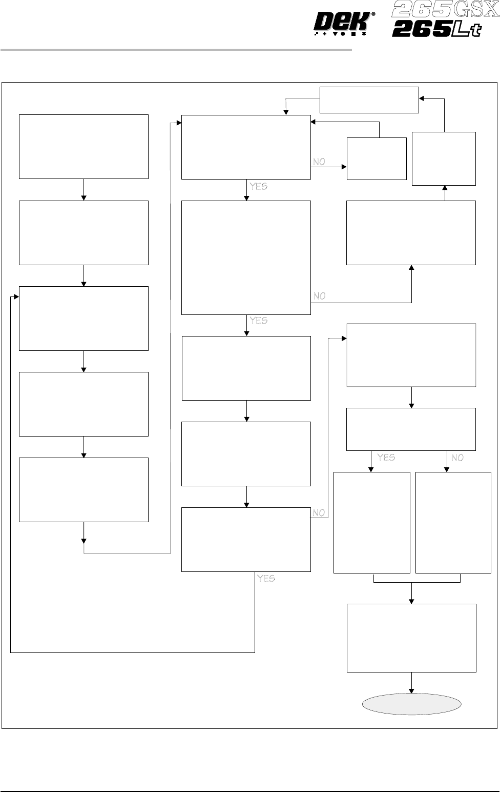
8.12 User Manual Software Version 6
2Di INSPECTION
MODULE OVERVIEW
Adjust Lighting:
Adjust so all board pads are
white with sharp edges and
the screen is seen clearly.
Add Limits Sets:
Set wide tolerances so no
alarms occur.
Add Site:
Name, Location Etc
Ensure all pads are within
the search box.
Set Globals as required:
2D Inspect Rate = 0
Learn Site / Learn Board:
Adjust board graphic ‘X’
and ‘Y’ accurately
Exit out
Auto Scale:
Determine the print closest
to 100% and auto scale on
that pad
Inspect Site:
Paste present data for all
pads are close to the same
value ?
If Board Inspect Type set to
Advance, all the paste
toggles white or yellow on
the board ?
More Sites to Teach ?
Add the rest of the sites
using the same light
settings as this first one
Print Board:
Step through the cycle until
a board is printed.
Is it a good print ?
Exit out
Place a clean
board into the
machine.
Clean screen
Re-adjust Lighting:
Adjust the LED’s to balance
the lighting
Run Product:
Have QC Calc ?
Reset the Globals:
Set the min sites/cycle.
Set 2D Inspect Rate.
Re-adjust the Limit Sets:
The customer may have to
adjust these settings a few
times until the proper
values are found.
SPC Data:
Collect SPC
data on the
2Di. From
this data
derive the
proper ‘limit
sets’ settings.
Trial & Error:
Increase the
‘limit sets’ and
use the data
when it alarms
to derive the
proper
settings.
DONE
New Pre-image taken
Figure 8-13 2Di Inspection Setup Guide
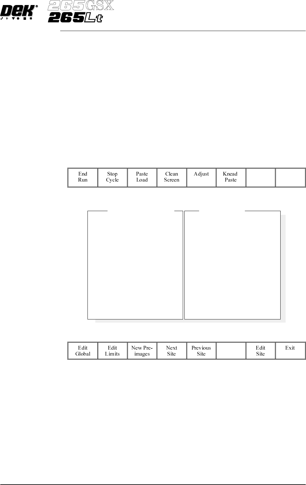
Adjustment During
Print Cycle
Most inspection parameters may be adjusted whilst a print cycle is in progress.
The parameters that may be adjusted are:
• Global Limits
• Limit Sets
• Site Parameters
NOTE
The site coordinate parameters are not available whilst a print cycle is in
progress.
To access the parameter adjustment menu during a print cycle select Adjust
Inspect.
Adjust
Inspect
The following window is displayed:
The New Pre-images button is only available if Pre-image is set to 1.
NOTE
If an error occurs when adjusting inspection parameters during a print cycle,
the adjustment page closes.
Any changes made are saved.
Software Version 6 User Manual 8.13
2Di INSPECTION
MODULE OVERVIEW
SiteName
SitePriority
StencilInspectType
BoardInspectType
SiteAlignment
LimitSetID
PasteScaling
SiteXCoord
SiteYCoord
SiteWidth
SiteHeight
IC27-1
General
Advanced
Advanced
XandY
Fine
1.00
39.4mm
71.2mm
3.00mm
4.00mm
2DInspectRate
StencilInspectType
BoardInspectType
Pre-image
Min.Sites/Cycle
WarningLimit
BlockageAction
BlockageClean
SmearAction
SmearClean
LowPasteAction
InspectAfterClean
PostPrintAlignment
No.Sites
1
Advanced
Advanced
Every
10
3
Auto
Mode2
Manual
Mode1
Re-print
Enabled
Performed
30
GlobalInspectParameters
SiteParameters