Dek-265GSX-User-Manual.pdf.pdf - 第281页
17. Select Run . Run 18. If the screen has not been changed the message ‘Screen has not been changed for this product’ is displayed, select Use Screen to continue. 19. Select Auto Board . Auto Board 20. The message ‘Load…
5.
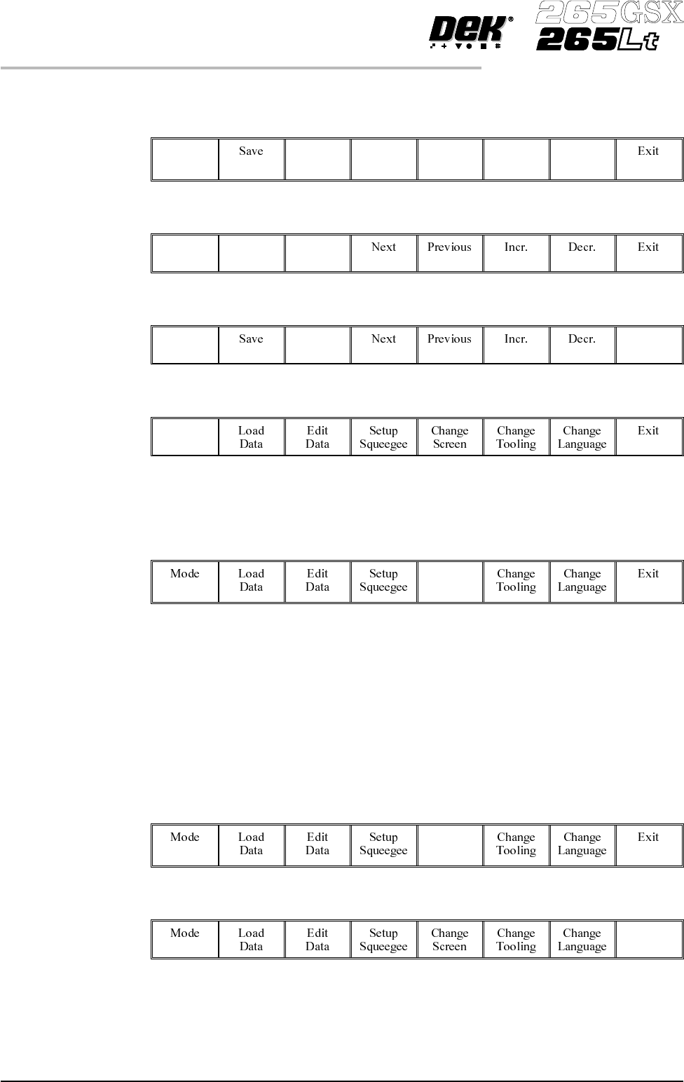
Using the Next, Previous, Incr. and Decr. keys, edit the current process
parameters for the new product.
Next Previous Incr. Decr.
6.
Press Save.
Save
7.
When the message ‘Board Data File Saved’ is displayed, press Exit.
Exit
8.
SelectMode until Stepappears in mode option of theprinterstatusdisplay.
Mode
If the required screen is already in the printer go to Step 16.
If the screen needs to be changed continue with Step 9.
9.
Select Change Screen.
Change
Screen
10.
When the message ‘Open Front Cover and Remove Screen’ is displayed
lift the printhead cover.
11. Remove the screen from the printer.
12. Fit the new screen into the printer ensuring the correct orientation of the
screen.
13. Lower the printhead cover.
14.
Press the System button on the control console.
15.
Select Change Screen.
Change
Screen
16.
Select Exit.
Exit
8.16 User Manual Software Version 6
2Di INSPECTION
2Di SETUP
17.
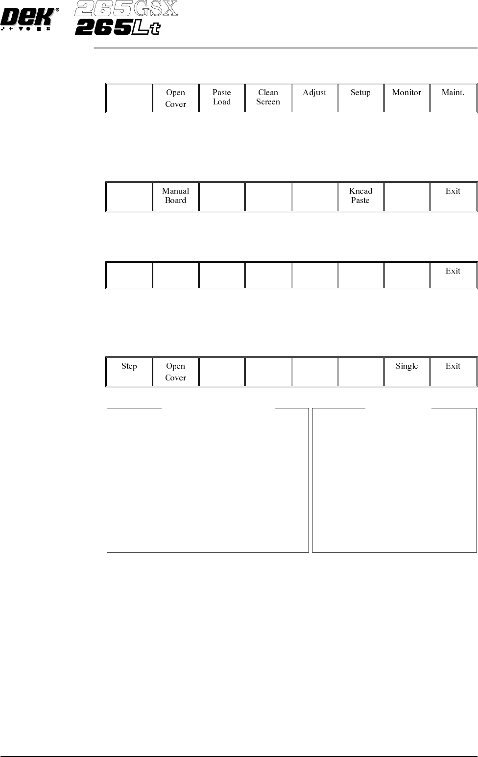
Select Run.
Run
18.
If the screen has not been changed the message ‘Screen has not been
changed for this product’ is displayed, select Use Screen to continue.
19.
Select Auto Board.
Auto
Board
20.
The message ‘Load board’ is displayed. Load board, select Confirm when
the board is loaded.
Confirm
21. Setup the board and screen fiducials.
22.
Select Inspect Setup. If this option is unavailable, check set prefs for 2D
Inspection enabled.
Inspect
Setup
NOTE
The windows in this procedure show the parameters and options available with
both screen and board inspect type set to advanced. If screen or board inspect
type is set to basic or none, certain parameters and options are not displayed.
CAUTION
FIDUCIAL POSITION. If during the print cycle, the position of board
fiducials are changed, the position of previous inspection sites (if any) may
be affected. Small changes are automatically compensated for, however
large changes, ie more than 3mm, require sites to be repositioned.
Software Version 6 User Manual 8.17
2Di INSPECTION
2Di SETUP
2D INSPECT RATE
STENCIL INSPECT TYPE
BOARD INSPECT TYPE
PRE-IMAGE
MIN SITES/CYCLE
WARNING LIMIT
BLOCKAGE ACTION
BLOCKAGE CLEAN
SMEAR ACTION
SMEAR CLEAN
LOW PASTE ACTION
INSPECTAFTER CLEAN
POST PRINTALIGNMENT
No. SITES
1
ADVANCED
ADVANCED
EVERY
10
3
MANUALACTION
MODE 1
MANUALACTION
MODE 2
RE-PRINT
ENABLED
PERFORMED
30
Global Inspect Parameters
SITE NAME
SITE PRIORITY
STENCIL INSPECT TYPE
BOARD INSPECT TYPE
SITE ALIGNMENT
LIMIT SITE I.D.
PASTE SCALING
SITE X COORD
SITE Y COORD
SITE WIDTH
SITE HEIGHT
QFP 1
GENERAL
ADVANCED
ADVANCED
X AND Y
FINE
1.00
84.5 mm
89.5mm
4.00 mm
4.00 mm
Site Parameters
Edit Global 1.
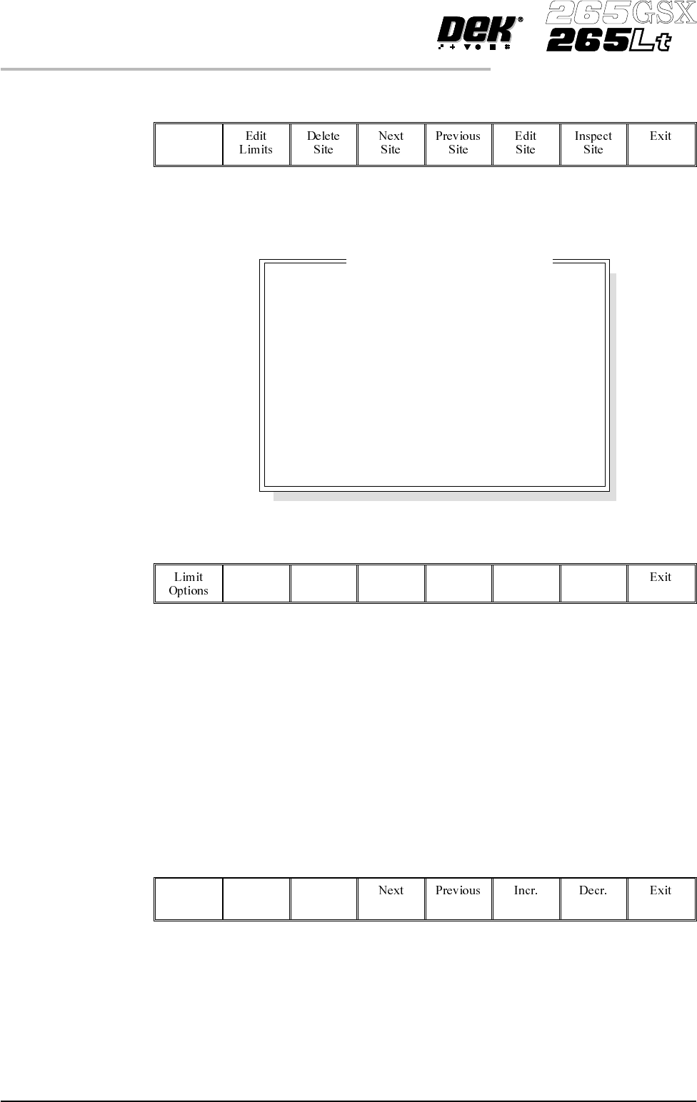
Select Edit Global.
Edit
Global
NOTE
Delete site is only available if at least one site exists already.
Next site and previous site are only available if at least two sites exist already.
2.
Enter the parameter values below using the Next, Previous, Incr. and Decr.
keys.
Next Previous Incr. Decr.
• Pre-image to Every
• Min Sites to 10
• Warning Limit to 20, this can be reduced later in ‘adjust inspect’.
• Blockage Action to Manual,this canbechangedlaterin ‘adjust inspect’.
• Smear Action to Manual, this can be changed later in ‘adjust inspect’.
A definition of all 2Di parameters and their values is given at the end of this
chapter.
On completion of successful setup, parameters can be adjusted to suit the
product.
3.
Select Limit Options.
Limit
Options
8.18 User Manual Software Version 6
2Di INSPECTION
2Di SETUP
Advanced
Advanced
Every
10
3
Manual
Mode 1
Manual
Mode 2
Manual
Enabled
Performed
Stencil Inspect Type
Board Inspect Type
Pre-image
Min. Sites/Cycle
Warning Limit
Blockage Action
Blockage Clean
Smear Action
Smear Clean
Low Paste Action
Inspect After Clean
Post Print Alignment
Edit Global Parameters