Dek-265GSX-User-Manual.pdf.pdf - 第287页
Edit Site 1. Select Edit Site . The edit site parameters window is displayed and the site name parameter is highlighted. Edit Site NOTE Delete site is only available if at least one site exists already. Next site and pre…
3.
Select Limit Options.
Limit
Options
These are usually set to enabled. If for any reason a particular inspection is not
required, set to disabled. If any global limit set options are disabled the
corresponding parameters are greyed out. These are limit set options, therefore
they are only active for this particular limit set. If a particular inspection is not
required for the whole product, this can be achieved in global limit options,
under edit globals, earlier in this chapter.
If either blockage or paste is set to disabled, volume is also disabled. Once
volume is disabled by this method it is not automatically enabled should both
blockageand paste be re-enabled. Volumemust be selected and set toenabled.
4.
Enter limit set options using Next, Previous, Incr. and Decr. keys.
Next Previous Incr. Decr.
5.
Select Exit.
Exit
6.
Select Save Limits.
The message ‘Saving Fiducial Data - Please Wait
Board data file saved’ is displayed.
Save
Limits
7.
Select Exit.
Exit
8.
Select Exit.
Exit
8.22 User Manual Software Version 6
2Di INSPECTION
2Di SETUP
Enabled
Enabled
Enabled
Enabled
Enabled
Enabled
Blockage
Smear
Paste
Alignment
Bridging
Volume
Site Limit Set Options
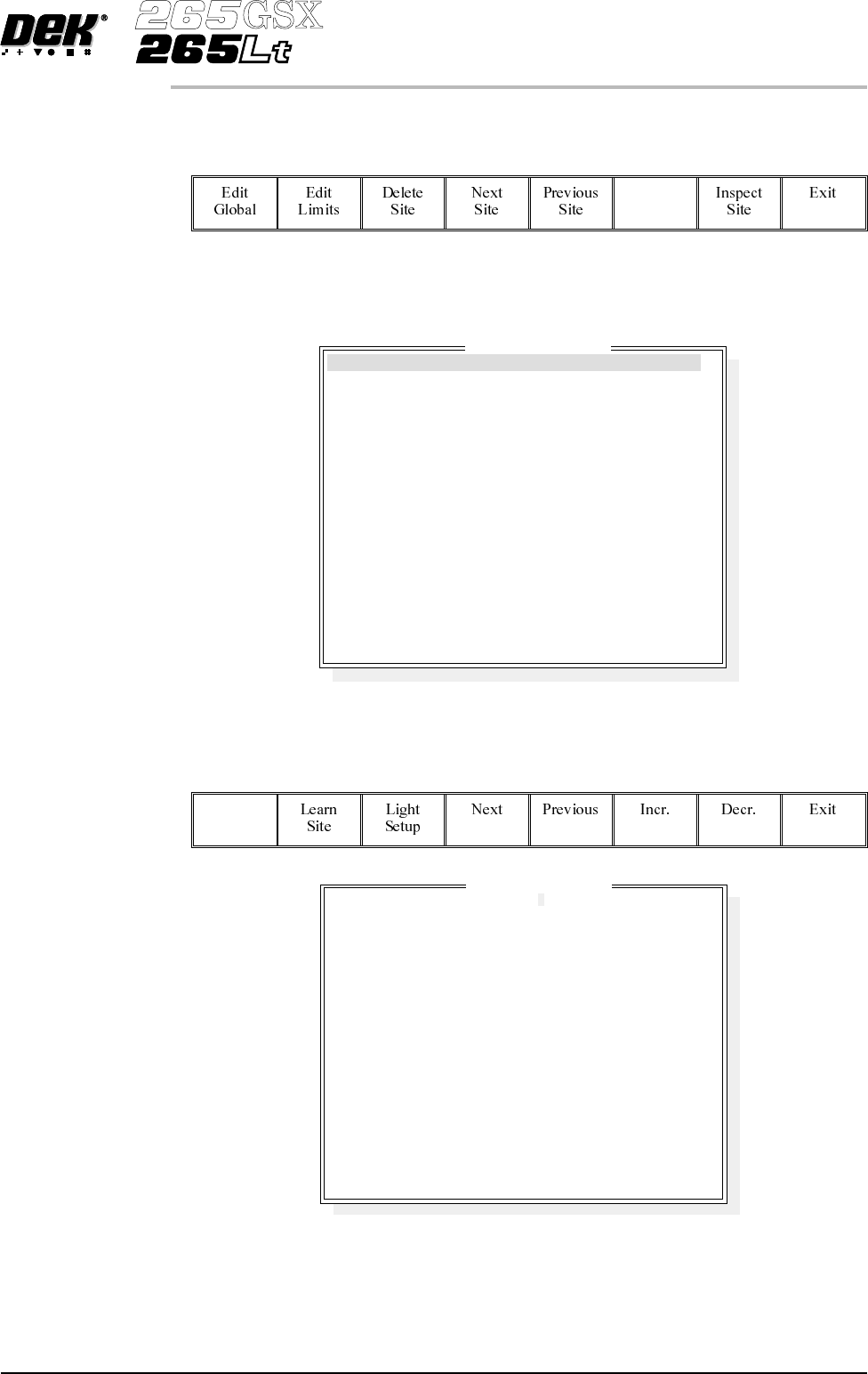
Edit Site 1.
Select Edit Site. The edit site parameters window is displayed and the site
name parameter is highlighted.
Edit
Site
NOTE
Delete site is only available if at least one site exists already. Next site and
previous site are only available if at least two sites exist already.
NOTE
Screen graphic and board graphic are only relevant to GSX/Lt machines.
2.
Select Add Site. The cursor flashes along side the site name parameter.
Add
Site
3.
Use the keyboard to enter the site name and press Enter.
NOTE
Site name may be any name up to 20 characters in length including spaces.
Software Version 6 User Manual 8.23
2Di INSPECTION
2Di SETUP
SITE 1
GENERAL
ADVANCED
ADVANCED
X and Y
COARSE
1.00
80.4 mm
86.4 mm
2.00 mm
2.00 mm
WHITE
0.00 mm
0.00 mm
BLACK
0.00 mm
0.00 mm
Edit Site Parameters
SITE NAME
SITE PRIORITY
STENCIL INSPECT TYPE
BOARD INSPECT TYPE
SITE ALIGNMENT
LIMIT SET ID
PASTE SCALING
SITE X COORD
SITE Y COORD
SITE WIDTH
SITE HEIGHT
SCREEN GRAPHIC
SCREEN GRAPHIC X
SCREEN GRAPHIC Y
BOARD GRAPHIC
BOARD GRAPHIC X
BOARD GRAPHIC Y
4.
Enter parameters using the Next, Previous, Incr. and Decr. keys.
Next Previous Incr. Decr.
5.
Highlight site limit ID using the Next and Previous keys.
Next Previous
6.
Select Incr.
Incr.
7.
Using Next Limit or Previous Limit keys, highlight the coarse limit set
created in either add limits or edit limits.
Next
Limit
Previous
Limit
8.
Select Use Limit.
Use
Limit
9. Measure the X and Y dimensions of the required site from the board or
screen.
NOTE
For the initial setup of 2Di use a single site. After the setup is complete add auto
learn features if required.
8.24 User Manual Software Version 6
2Di INSPECTION
2Di SETUP
DEFAULT
FINE
COARSE
Limit Sets