Dek-265GSX-User-Manual.pdf.pdf - 第296页
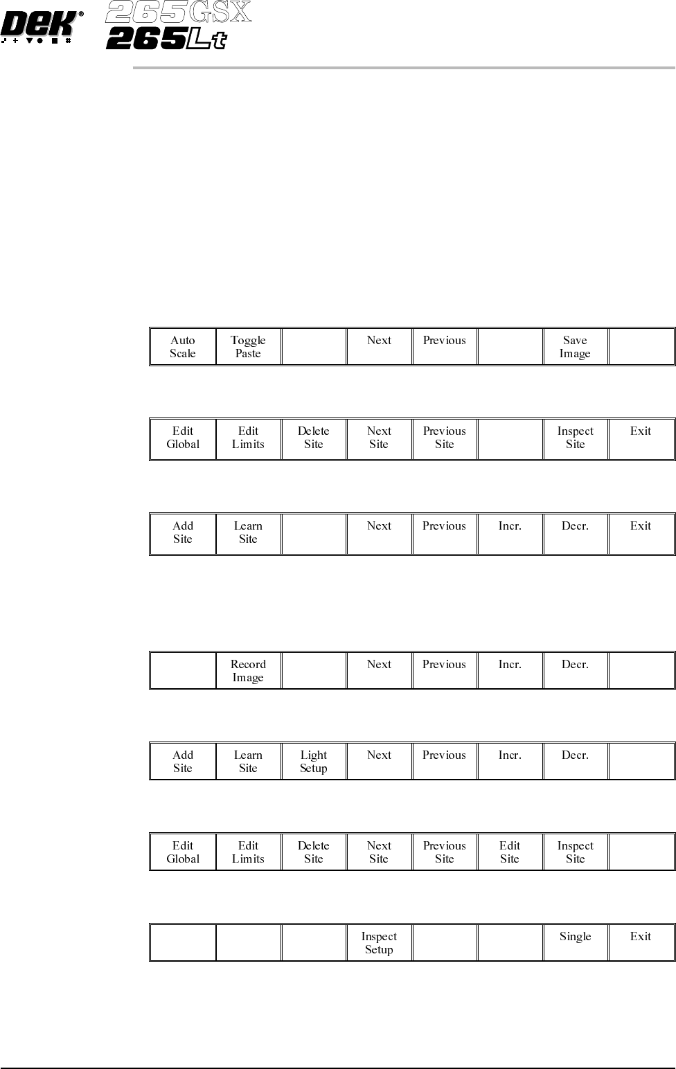
18. Load a clean board onto the rails and clean the screen. 19. Repeat Steps 5-9. 20. Select Auto Scale . Auto Scale Selecting auto scale automatically adjusts the paste scaling value for the current site, to cause the v…
9b. Ensure that the paste display overlay coincides with the presence of paste. If
this is correct go to Step 20. If this is incorrect, note the position of the
non-existant paste and continue with Step 10.
NOTE
If the paste display overlay coincides with the presence of paste, any poor
inspection results are due to process problems and not 2Di setup.
9c. Ensure that the inspection results are consistent with the amount of paste on
the pad. If this is correct go to Step 20. If this is incorrect continue with
Step 10.
10.
Select Exit.
Exit
11.
Select Edit Site.
Edit
Site
12.
Select Light Setup.
Light
Setup
13. Adjust the lighting parameters to improve the lighting conditions in the
suspect areas.
14.
Select Exit.
Exit
15.
Select Exit.
Exit
16.
Select Exit.
Exit
17.
Select Step to remove the board from the machine.
Step
Software Version 6 User Manual 8.31
2Di INSPECTION
2Di SETUP
18. Load a clean board onto the rails and clean the screen.
19. Repeat Steps 5-9.
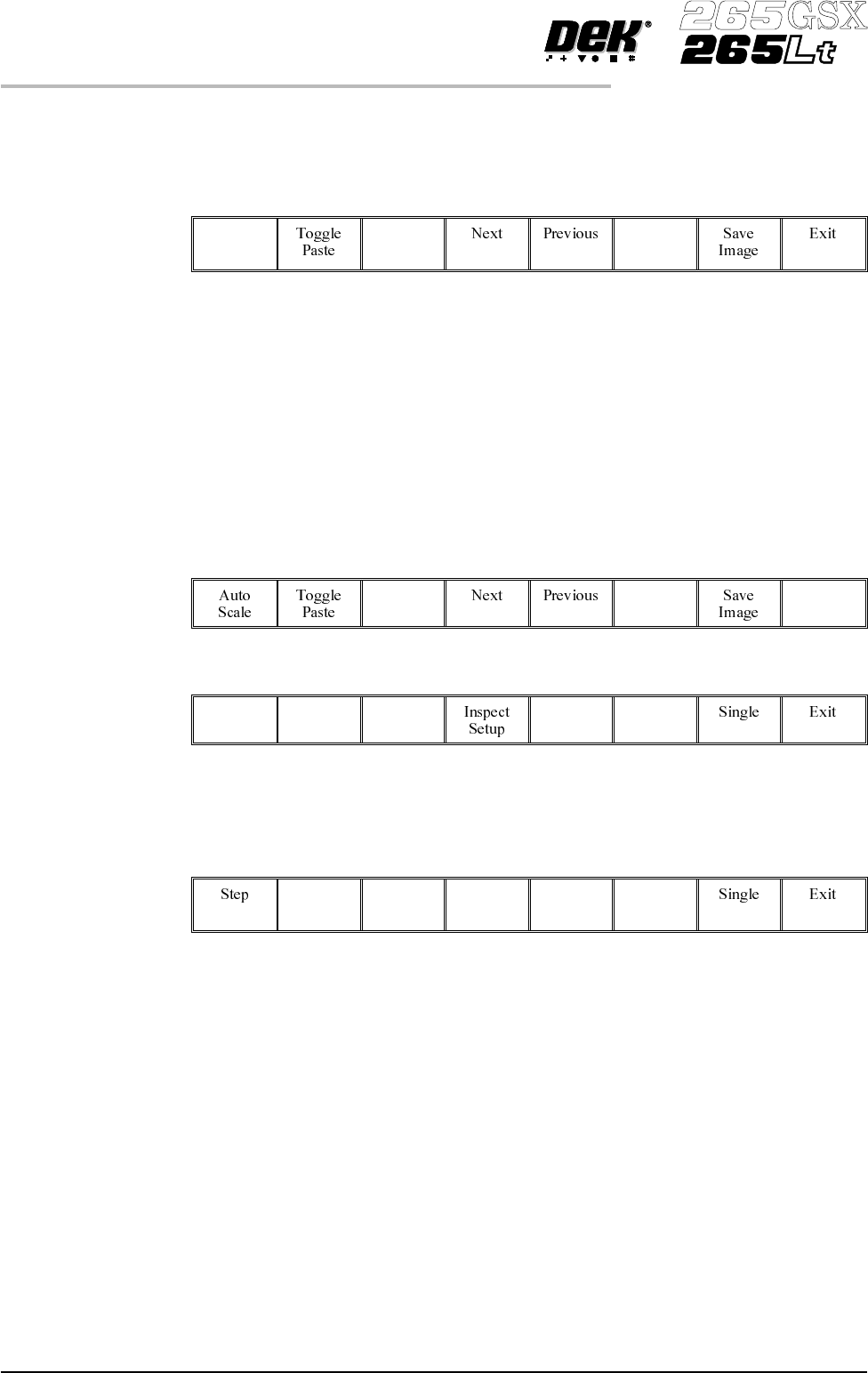
20.
Select Auto Scale.
Auto
Scale
Selecting auto scale automatically adjusts the paste scaling value for the current
site, to cause the value of paste present, on the pad currently selected in the
inspection result list, to be reported as 100%. The inspection results window is
updated accordingly. If the calculated value for paste scaling falls outside the
range of allowable values, an error window is displayed and the paste scaling
value is set to the limit nearest the calculated value. However, if the currently
selected paste present value is zero, no adjustment of the paste scaling value
takes place and an error window is displayed. A prompt is displayed giving the
new scaling factor value each time it is changed. The auto scale button is only
present if board inspection is being performed.
21.
Select Exit.
Exit
22.
Select Step to remove the board from the machine.
Step
23. Clean the board and screen.
24. Run through the print cycle in step mode until inspect setup is displayed.
25.
Select Inspect Setup.
Inspect
Setup
8.32 User Manual Software Version 6
2Di INSPECTION
2Di SETUP
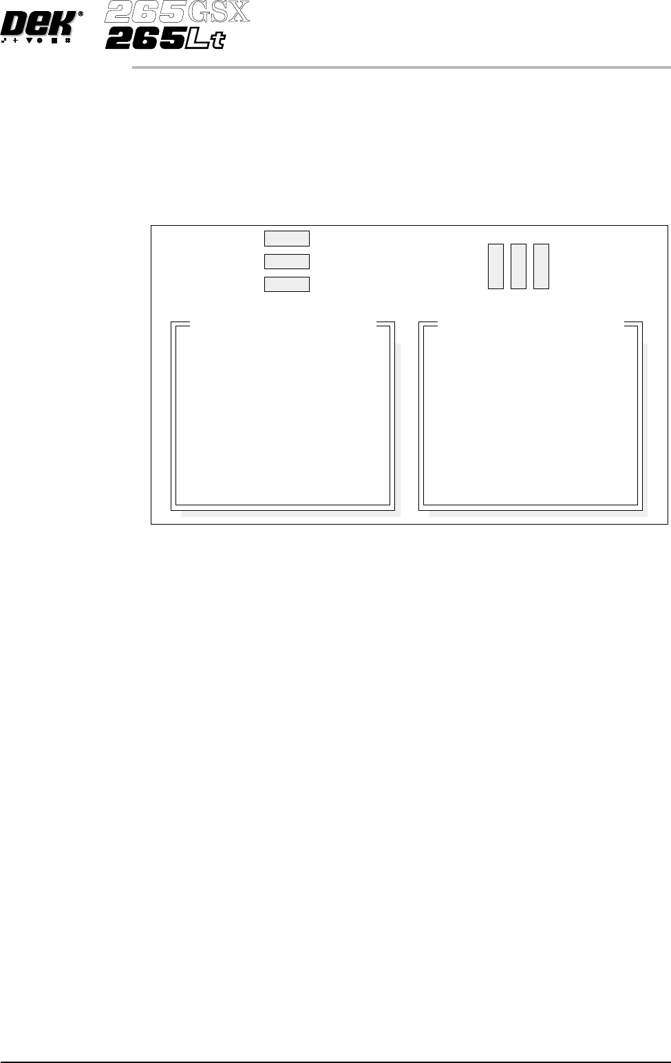
26. Carry out Section Edit Site and create all required sites, using the same
lighting parameters as before (see Auto Learn).
NOTE
For the silver camera only, if the new sites pads and/or apertures are at 90
degrees to the original pads and/or apertures, interchange the lighting
parameters inner LR with inner FR and outer LR with outer FR, on the board
and/or screen, as shown below.
27. On completion carry out Section Inspect.
28. Set the required 2D inspect rate and the Min site/cycle parameters in edit
global.
29. This completes the 2Di setup. Commence print run in auto mode.
NOTE
During production use adjust inspect to fine tune the inspection process.
Software Version 6 User Manual 8.33
2Di INSPECTION
2Di SETUP
Original Site
New Site
8
9
10
11
12
8
9
10
11
12
Inspection Lighting Parameters
Screen Vertical
Screen Inner LR
Screen Inner FR
Screen Outer LR
Screen Outer FR
Board Vertical
Board Inner LR
Board Inner FR
Board Outer LR
Board Outer FR
8
10
9
12
11
8
10
9
12
11
Inspection Lighting Parameters
Screen Vertical
Screen Inner LR
Screen Inner FR
Screen Outer LR
Screen Outer FR
Board Vertical
Board Inner LR
Board Inner FR
Board Outer LR
Board Outer FR