Dek-265GSX-User-Manual.pdf.pdf - 第298页
Auto Learn Prior to carrying out auto learn, the 2Di setup described in the preceding pages, must have been carried out. 1. From the Section Auto Learn, under Module Overview, at the front of this chapter, identify the p…
26. Carry out Section Edit Site and create all required sites, using the same
lighting parameters as before (see Auto Learn).
NOTE
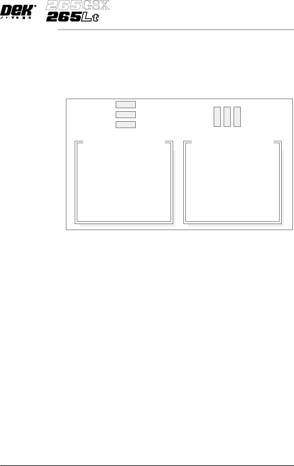
For the silver camera only, if the new sites pads and/or apertures are at 90
degrees to the original pads and/or apertures, interchange the lighting
parameters inner LR with inner FR and outer LR with outer FR, on the board
and/or screen, as shown below.
27. On completion carry out Section Inspect.
28. Set the required 2D inspect rate and the Min site/cycle parameters in edit
global.
29. This completes the 2Di setup. Commence print run in auto mode.
NOTE
During production use adjust inspect to fine tune the inspection process.
Software Version 6 User Manual 8.33
2Di INSPECTION
2Di SETUP
Original Site
New Site
8
9
10
11
12
8
9
10
11
12
Inspection Lighting Parameters
Screen Vertical
Screen Inner LR
Screen Inner FR
Screen Outer LR
Screen Outer FR
Board Vertical
Board Inner LR
Board Inner FR
Board Outer LR
Board Outer FR
8
10
9
12
11
8
10
9
12
11
Inspection Lighting Parameters
Screen Vertical
Screen Inner LR
Screen Inner FR
Screen Outer LR
Screen Outer FR
Board Vertical
Board Inner LR
Board Inner FR
Board Outer LR
Board Outer FR
Auto Learn Prior to carrying out auto learn, the 2Di setup described in the preceding pages,
must have been carried out.
1. From the Section Auto Learn, under Module Overview, at the front of this
chapter, identify the position of Site 1 for the required feature.
2. Carry out Section Edit Site for Site 1 coordinates.
3. Carry out Sub Section Lighting Setup, using the same parameters as
previous.
4. Carry out Sub Section Learn Site paras 1-4.
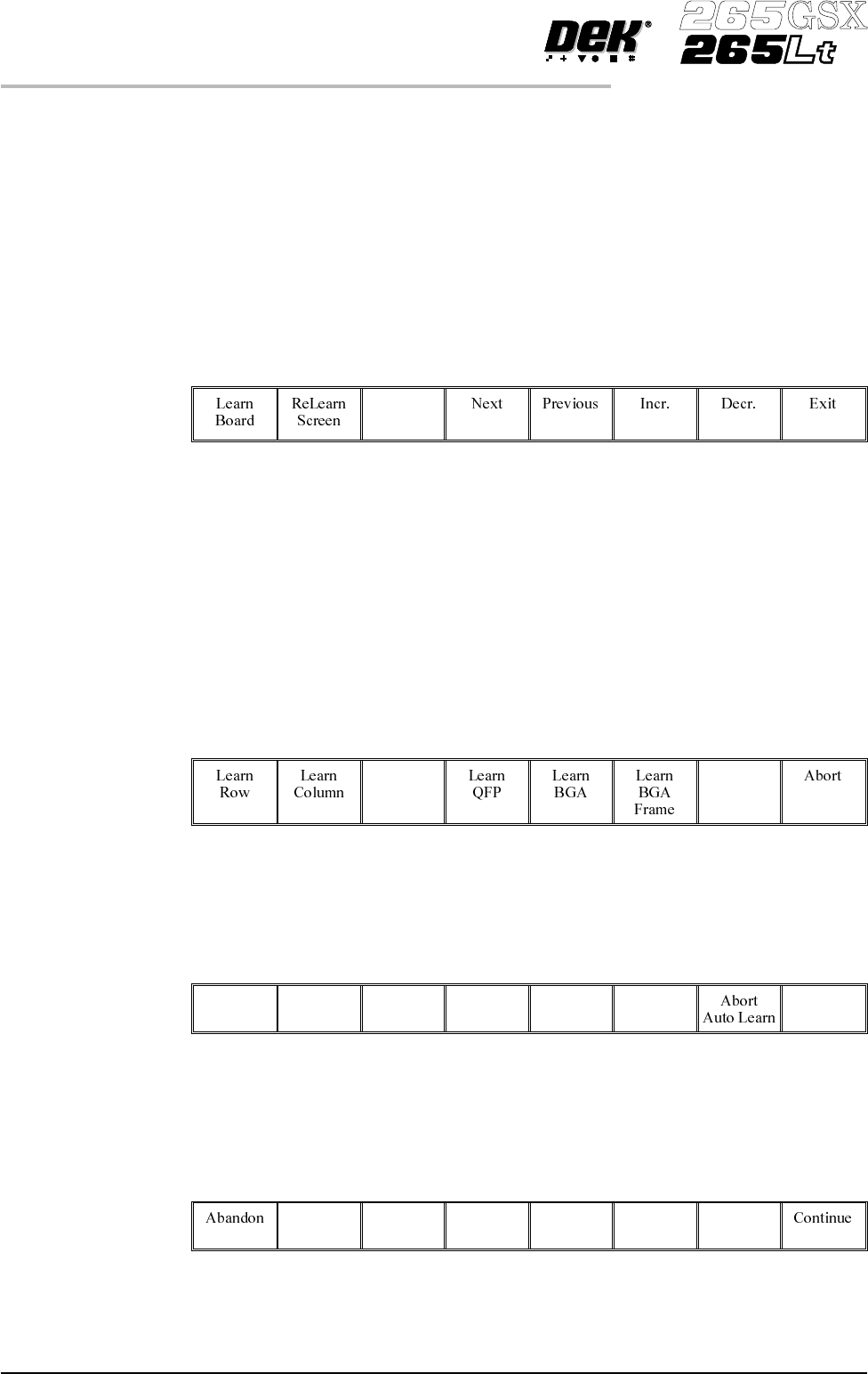
5.
Select Auto Learn.
Auto
Learn
The message ‘Select Component type to Auto Learn:’ is displayed. The
following messages appear beneath this message in rotation:
‘Row - Start at left most end of horizontal’
‘Col - Start at topmost end of vertical’
‘QFP - (Quad Flat Pack) - Start at left most end of top horizontal line’
‘BGA - (Ball Grid Array) - Start at top left corner of array’
‘BGA Frame - Start at top left corner of array frame’
6. Select required component to learn.
The message bar reports the progress of the auto learn as a set of sites of the
appropriate type are created and learnt. The original site, and each site that is
created, is given the same name as the original site, but with a ‘~’ symbol
followed by a three digit number in sequence. While creation and learning is in
progress the following menu bar is displayed:
As each new site is created and learnt, the newly created name and data is
displayed in the Edit Site Parameters window.
If Abort Auto Learn is selected the message ‘Site creation and learning
interrupted; do you want to . . . is displayed. The following menu bar is
displayed:
IfAbandonisselectedanysitesthathavebeencreatedaredeleted. If Continue is
selected the auto learn resumes, creating and learning sites.
8.34 User Manual Software Version 6
2Di INSPECTION
2Di SETUP
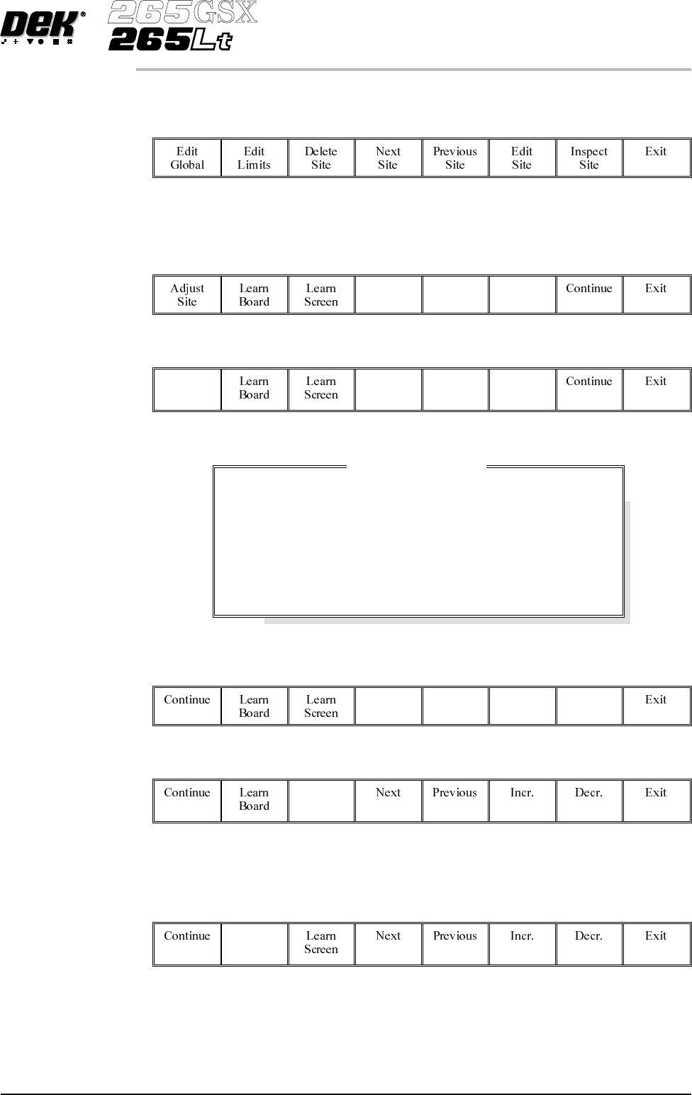
7. On completion of a successful auto learn of the selected component, the
following menu bar is displayed:
8. Repeat Steps 1 to 7 for further auto learn features.
9. While creating and learning the sites for a device, if a site is not positioned
correctly for learning, the following menu bar is displayed:
10.
Select Adjust Site. The learn site parameters window is displayed.
Adjust
Site
11.
Adjust site parameters as required using Next, Previous, Incr. and Decr.
keys.
Next Previous Incr. Decr.
12.
Select Learn Screen.
Learn
Screen
13.
The message ‘Screen Learnt’ is displayed. If the message ‘....Screen Not
Learnt’ is displayed, edit the site parameters and select Learn Screen.
14.
Select Learn Board.
Learn
Board
15.
The message ‘Board Learnt’ is displayed. If the message ‘....Board Not
Learnt’ is displayed, edit the site parameters and select Learn Board.
Software Version 6 User Manual 8.35
2Di INSPECTION
2Di SETUP
SITE X COORD
SITE Y COORD
SITE WIDTH
SITE HEIGHT
SCREEN GRAPHIC X
SCREEN GRAPHIC Y
BOARD GRAPHIC X
BOARD GRAPHIC Y
52.0
36.5
2.00
2.00
-0.01
-0.01
0.00
0.00
mm
mm
mm
mm
mm
mm
mm
mm
Learn Site Parameters