Dek-265GSX-User-Manual.pdf.pdf - 第36页
9. If an Adjustable Screen Spacer is to be used proceed to Step 10. Fit the new screen into the printhead ensuring the correct orientation of the screen. For edge justified screen images push the screen fully to the rear…
CAUTION
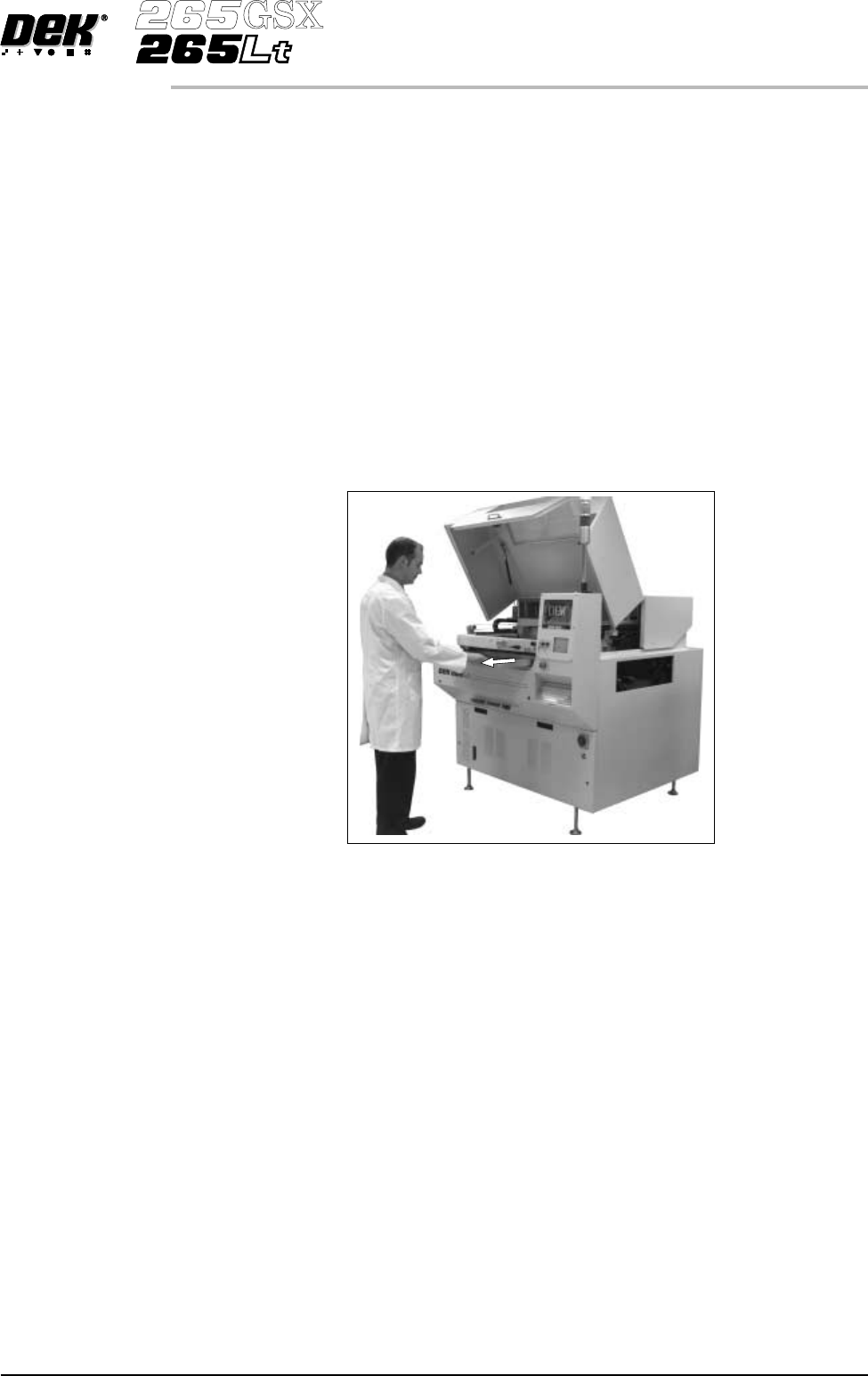
SCREEN EXTRACTOR ROD. When the screen removal mechanism is
being used and the extraction rod is extended (knob has been pulled
forward), care should be taken not to bend the extraction rod by pushing it
sidewaysor closingthefront cover. Distortionof the extractionrod impairs
the functioning of the screen removal mechanism.
ADJUSTABLE SCREEN SPACER. If an adjustable screen spacer has
been placed in the machine behind the screen, care should be taken when
removing the screen to avoid the spacer falling from the chase and causing
injury to the operator or damage to the machine.
4. If an Adjustable Screen Spacer is in the machine proceed to Step 5. Remove
the screen from the printer proceed to Step 9.
5. Pull the screen slowly forward until the rear edge of the screen, but NOT the
adjustable screen spacer, has just cleared the chase rails.
6. Lower the rear of the screen slightly so that it disengages from the adjustable
screen spacer.
7. Remove the screen from the machine.
8. Slowly remove the adjustable screen spacer from the machine.
Software Version 6 User Manual 1.19
MACHINE PROGRAMMING
STAGE 5B
9. If an Adjustable Screen Spacer is to be used proceed to Step 10.
Fit the new screen into the printhead ensuring the correct orientation of the
screen. For edge justified screen imagespushthescreenfullytotherear. For
centre justified screen images correctly position the screen using the
graduated scale. Proceed to Step 14.
NOTE
For the adjustable Screen Spacer setup, see Technical Reference Manual,
Screens and Screen Images Chapter.
10. Slide the adjustable screen spacer partly into the chase, with the jack screws
facing towards the rear of the machine.
11. Slide the screen into the chaseuntilitengageswiththescreencatch plates of
the adjustable screen spacer.
12. Slide the screen and spacer towards the rear of the chase until the spacer
makes contact with the chase stops.
13. Press gently against the front of the screen, to ensure that there is no gap
between the screen and spacer or the spacer and chase stops.
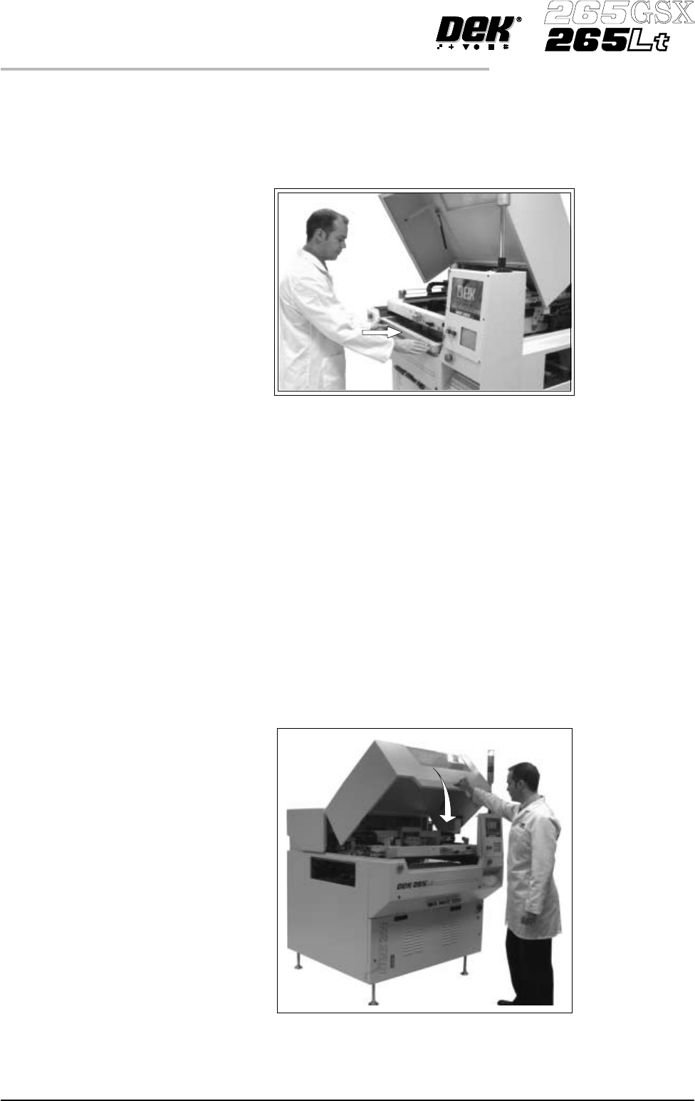
14. Lower the printhead cover.
1.20 User Manual Software Version 6
MACHINE PROGRAMMING
STAGE 5B

15.
Press the System button on the control console.
For edge justified screen images the screen is automatically clamped in
place, providing the screen has been pushed fully in against the stops.
16.
For centre justified screen images only, press Confirm, the screen is
automatically clamped in place.
17. Continue to Stage 6 - Tooling Setup.
CAUTION
SCREEN NOT LOADED. Pressing Confirm without a screen loaded,
could result in serious machine damage.
Software Version 6 User Manual 1.21
MACHINE PROGRAMMING
STAGE 5B