Dek-265GSX-User-Manual.pdf.pdf - 第48页
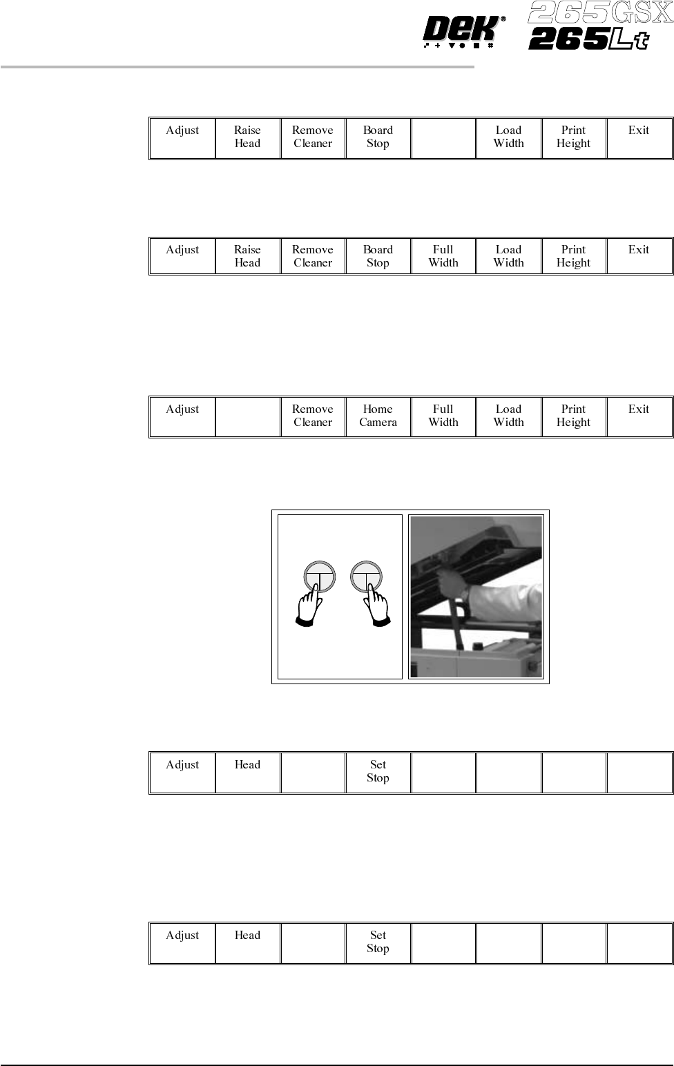
9. Select Board Width (F5). Board Width 10. Select Board Stop (F4). The camera moves to the board stop position. The board stop on the camera extends. 11. Select Raise Head (F2). Raise Head 12. Raise the printhead using …
5. The vacuum box can now be fitted into the appropriate location holes in the
tooling plate. Ensure that the vacuum box is placed into the correct set of
holes, taking regard of the type of screen being used and hence the position
of the fixed rail.
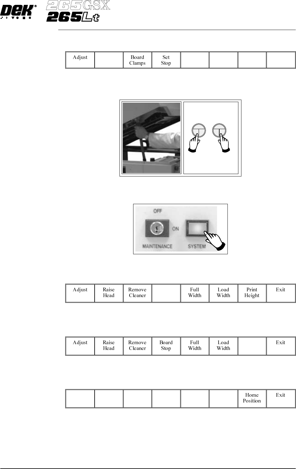
6.
Select Head (F2).
Head
7. Remove the head prop. Lower the printhead using two button control.
8.
Press the System button.
Software Version 6 User Manual 1.31
MACHINE PROGRAMMING
STAGE 6B
9.
Select Board Width (F5).
Board
Width
10.
Select Board Stop (F4).
The camera moves to the board stop position. The board stop on the camera
extends.
11.
Select Raise Head (F2).
Raise
Head
12. Raise the printhead using two button control. Fit the head prop.
13.
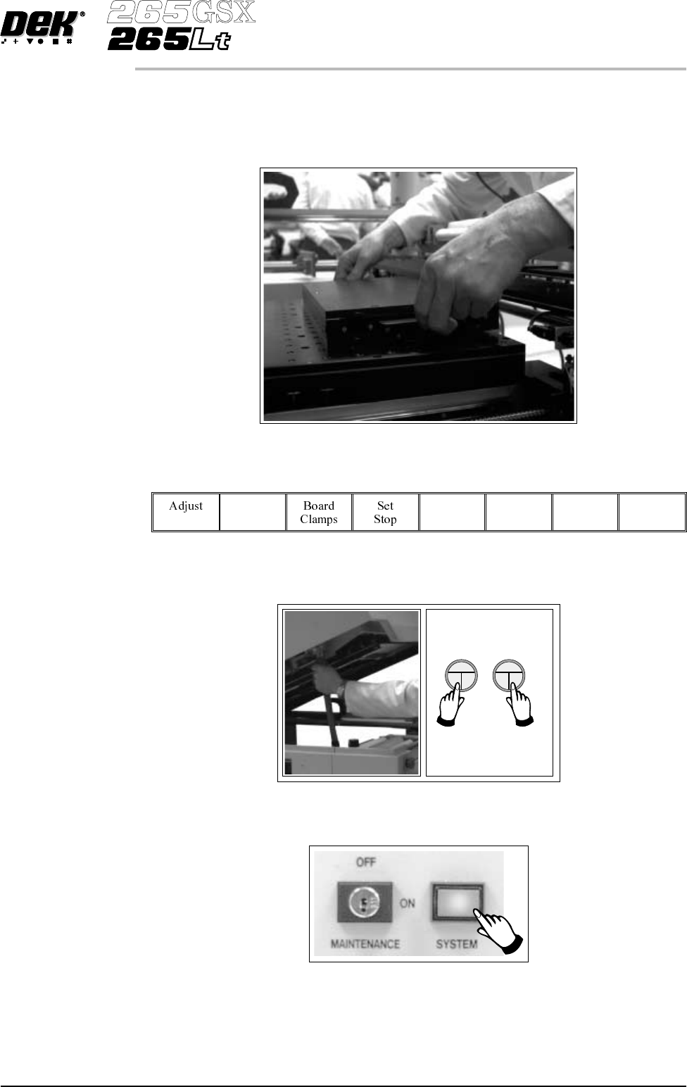
Select Board Clamps (F3), to open the clamps.
Board
Clamps
14. Slide a board along the rails to abut the board stop.
15.
Select Board Clamps (F3), to close the clamps.
Board
Clamps
1.32 User Manual Software Version 6
MACHINE PROGRAMMING
STAGE 6B
16.
Select Head (F2).
Head
17. Remove the head prop. Lower the printhead using two button control.
18.
Press the System button.
19.
Select Home Camera (F4).
Home
Camera
20.
Select Print Height (F7).
Print
Height
21.
Select Raise Head (F2).
Raise
Head
Software Version 6 User Manual 1.33
MACHINE PROGRAMMING
STAGE 6B