Dek-265GSX-User-Manual.pdf.pdf - 第68页
STAGE 6E Tooling Setup - AutoFlex The correct pins for each product are selected automatically when the board size parameters are programmed into the board file. If the pin configuration needs to be changed, for example …
39.
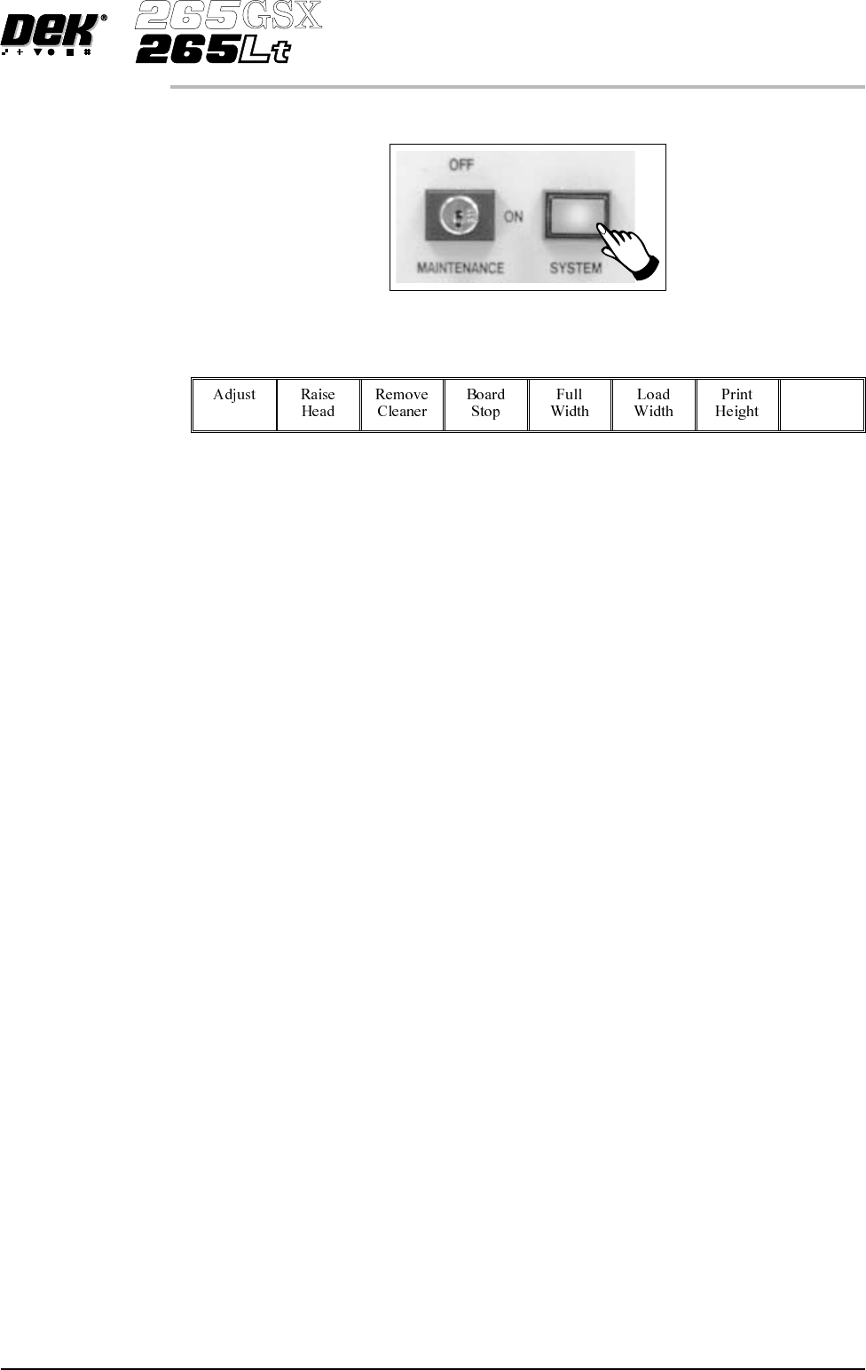
Press the System button.
40.
Select Exit (F8).
Exit
41. Go to Stage 7.
Software Version 6 User Manual 1.51
MACHINE PROGRAMMING
STAGE 6D
STAGE 6E
Tooling Setup - AutoFlex
The correct pins for each product are selected automatically when the board size
parameters are programmed into the board file. If the pin configuration needs to
be changed, for example if a support pin coincides with the position of an
underside component and needs to be removed, from the setup page:
1.
Select Change Tooling (F6).
Change
Tooling
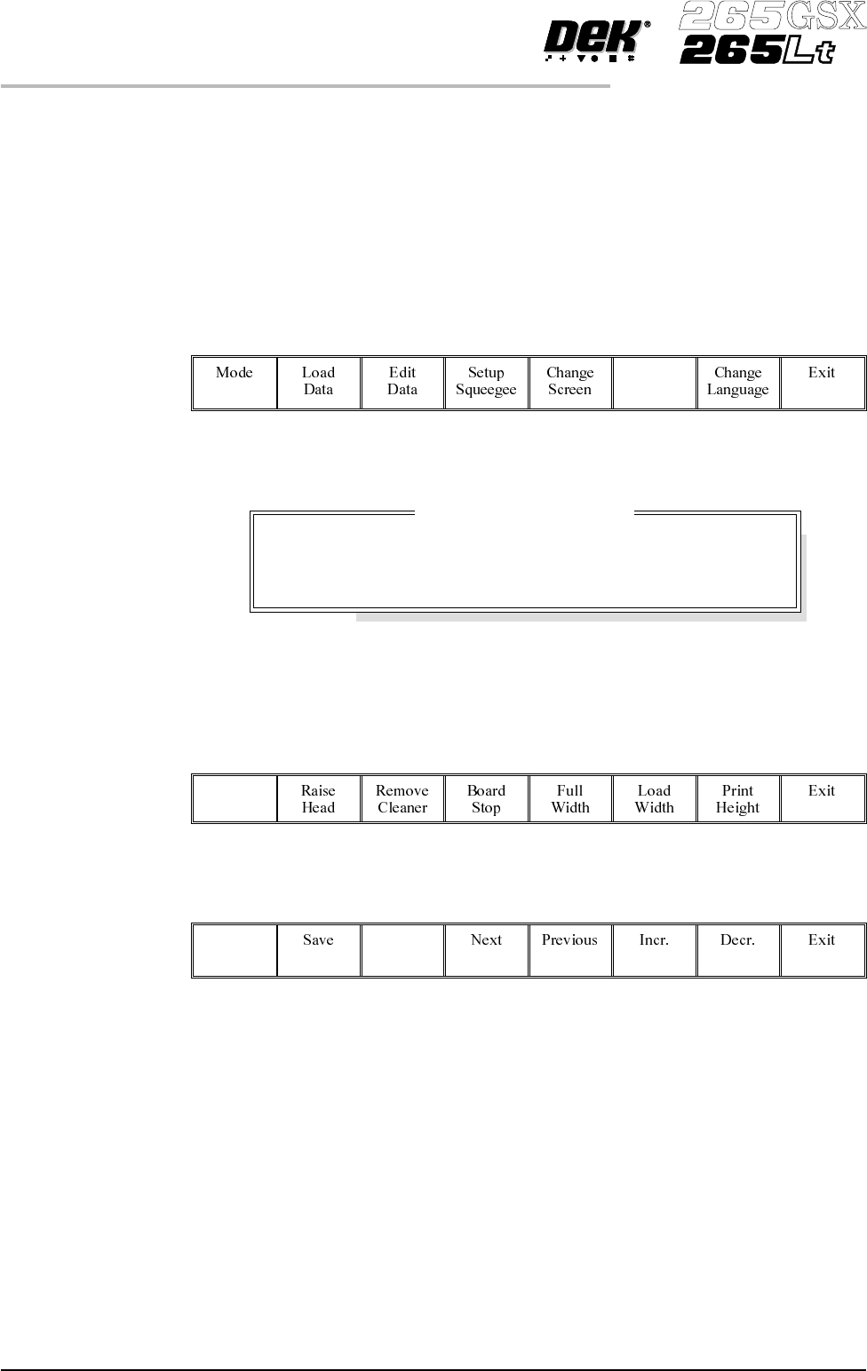
The Change Tooling Parameters window is displayed:
The parameters are not active.
2.
Select Adjust (F1). The parameters are now active.
Adjust
3.
Select Change Autoflex (F1).
Change
Autoflex
1.52 User Manual Software Version 6
MACHINE PROGRAMMING
STAGE 6E
Change Tooling Parameters
BOARD WIDTH
BOARD STOP X
BOARD STOPY
216.0
125.0
142.6
mm
mm
mm
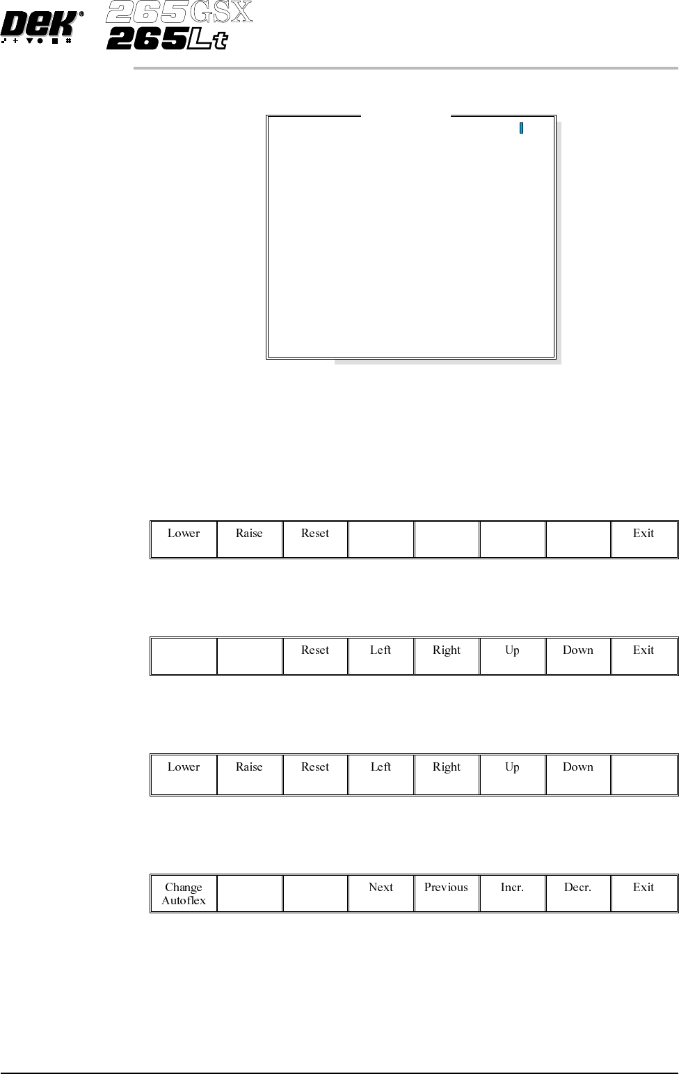
The Autoflex Matrix window is displayed:
The Autoflex pin matrix has already been setup for this product from the board
dimensions.
4.
Use the Left, Right, Up and Down keys (F4 -F7), to select the pin positions
required for editing.
Left Right Up Down
5.
Use the Lower and Raise keys (F1 - F2), to select or deselect the pins.
Lower Raise
6.
Select Exit (F8).
Exit
7.
Select Save (F2).
Save
Software Version 6 User Manual 1.53
MACHINE PROGRAMMING
STAGE 6E
Autof
l
ex Matr
i
x
14
13
12
11
10
9
8
7
6
5
4
3
2
1
A
B
C
D
E
F
G
H
I
J
K
L
M
N
O
---------------
---------------
---------------
---------------
---------------
---------------
---------------
---------------
---------------
---------------
---------------
---------------
---------------
---------------