Dek-265GSX-User-Manual.pdf.pdf - 第74页
33. Select Board Clamps (F3), to open the clamps. Board Clamps 34. Remove the board from the rails. 35. Select Head (F2). Head 36. Remove the head prop. Lower the printhead using two button control. 37. Press the System …
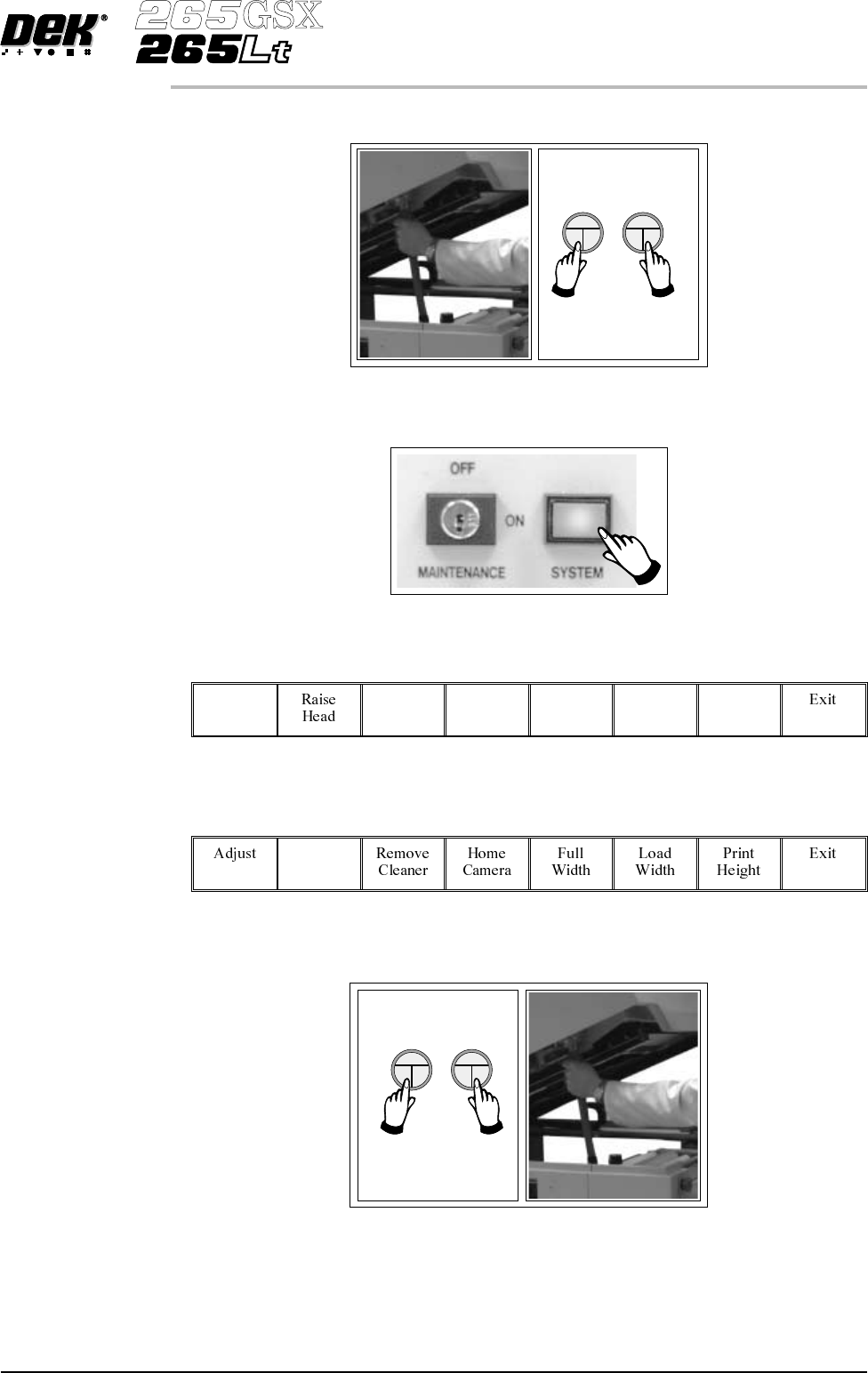
28. Remove the head prop. Lower the printhead using two button control.
29.
Press the System button.
30.
Select Home Position (F7).
Home
Position
31.
Select Raise Head (F2).
Raise
Head
32. Raise the printhead using two button control. Fit the head prop.
Software Version 6 User Manual 1.57
MACHINE PROGRAMMING
STAGE 6E
33.
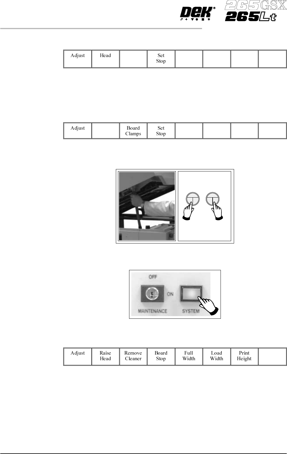
Select Board Clamps (F3), to open the clamps.
Board
Clamps
34. Remove the board from the rails.
35.
Select Head (F2).
Head
36. Remove the head prop. Lower the printhead using two button control.
37.
Press the System button.
38.
Select Exit (F8).
Exit
39. Go to Stage 7.
1.58 User Manual Software Version 6
MACHINE PROGRAMMING
STAGE 6E
STAGE 6F
Tooling Setup - Fine Pitch AutoFlex
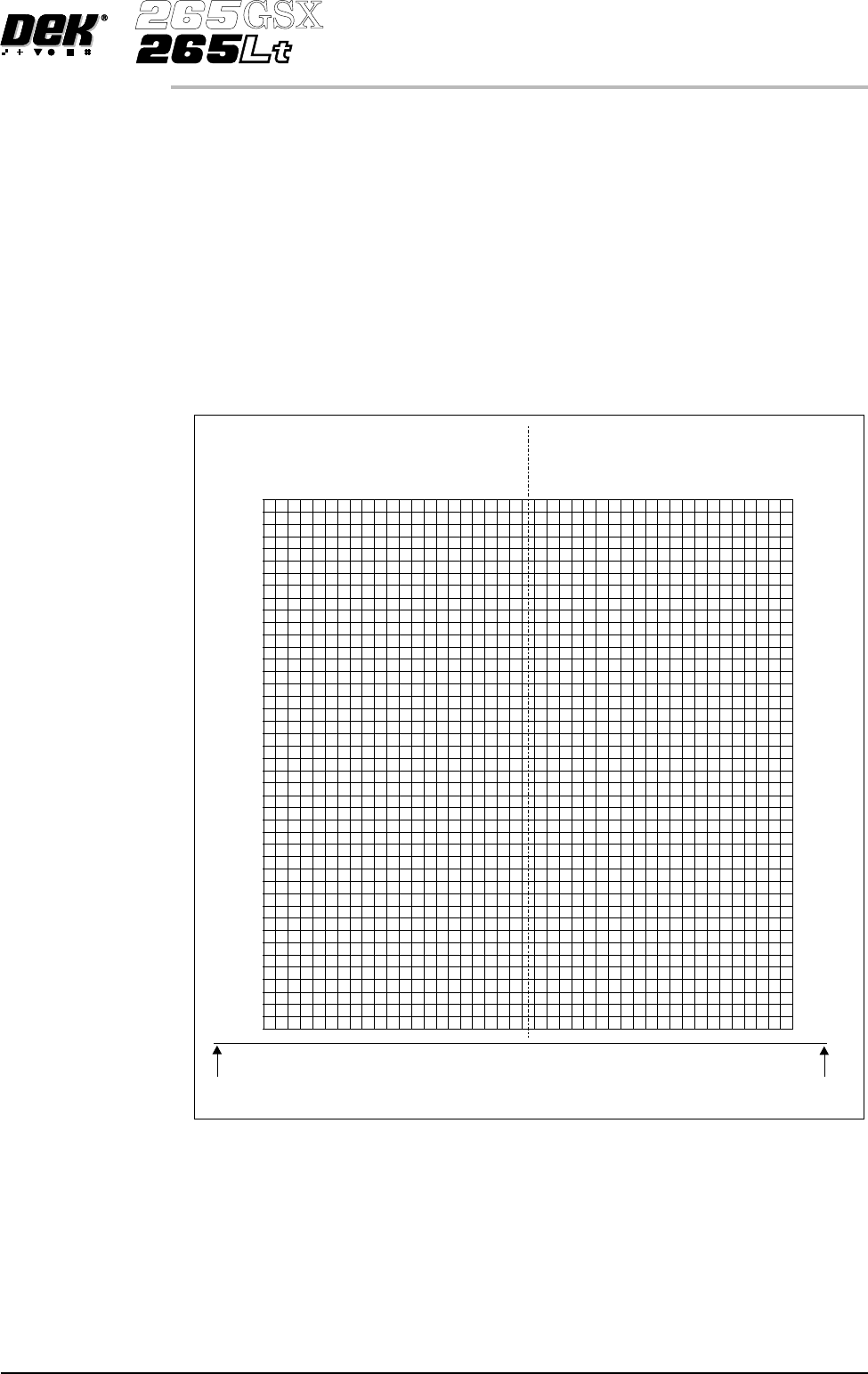
1. Place the PCB on a flat surface, component side up.
2. Position the acetate template, supplied with the tooling, over the PCB. Align
the centre of the PCB with the centreline of the template. Align the front
edge of the PCB with the line on the template.
3. Using the grid co-ordinates marked on the template, select which pins need
to be raised and which pins need to be lowered.
Software Version 6 User Manual 1.59
MACHINE PROGRAMMING
STAGE 6F
-236.5
-225.5
-214.5
-203.5
-192.5
-181.5
-170.5
-159.5
-148.5
-137.5
-126.5
-115.5
-104.5
-93.5
-82.5
-71.5
-60.5
-49.5
-38.5
38.5
49.5
60.5
71.5
82.5
93.5
104.5
115.5
126.5
137.5
148.5
159.5
170.5
181.5
192.5
203.5
214.5
225.5
236.5
487.5
476.5
465.5
454.5
443.5
432.5
421.5
410.5
399.5
388.5
377.5
366.5
355.5
344.5
333.5
322.5
311.5
300.5
289.5
278.5
267.5
256.5
245.5
234.5
223.5
212.5
201.5
190.5
179.5
168.5
157.5
146.5
135.5
124.5
113.5
102.5
91.5
80.5
69.5
58.5
47.5
36.5
25.5
14.5
-27.5
27.5
-16.5
16.5
-5.5
5.5
1
A
R
A
Q
A
P
A
O
A
N
A
M
A
L
A
K
A
J
A
I
A
H
A
G
A
F
A
E
A
D
A
C
A
B
A
A
ZYXWVUT
S
R
Q
P
O
NMLKJ I H
G
FED
millimetres
millimetres
millimetres
C
B
A
FRONT EDGE
OF BOARD
FRONT EDGE
OF BOARD
CENTRE LINE
OF BOARD
USAGE: 1. FLIP BOARD LEFT TO RIGHT
2. PLACE BOARD UNDER FILM
3. ALIGN CENTRE OF BOARD WITH CENTRE LINE ON FILM
4. ALIGN FRONT EDGE OF BOARDWITH LINE ON FILM
5. READ OFF GRID REFERENCES AND USE IN BOARD FILE
Note 2: THE FIGURES ACROSSTHE TOP OFTHE TEMPLATE
ARE REFERENCED TO THE CENTRE LINE OF THE BOARD
WHEREAS THE MMI MATRIX IS REFERENCED TO THE LEFT
OR RIGHT FRONT CORNER OF THE BOARD
Note 1: THE FIGURES DOWN THE RIGHT HAND SIDE OF THETEMPLATE
CORRESPOND TO THE FIGURES ON THE MMI MATRIX
AND REPRESENT THE DISTANCE FROM THE FRONT
EDGE OF THE BOARD
2
3
4
5
6
7
8
9
10
11
12
13
14
15
16
17
18
19
20
21
22
23
24
25
26
27
28
29
30
31
32
33
34
35
36
37
38
39
40
41
42
43
44