Dek-265GSX-User-Manual.pdf.pdf - 第78页
(ii). Using the numeric keypad enter the new value. (iii). Press Enter on the keyboard. (iv). Repeat Steps 8, 9a or 9b for each parameter. 10. Select either Lower Block (F1) or Raise Block (F2) as required. Lower Block R…
There are three ways of changing the pin configuration, as follows:
• Changing an area to either pins up or pins down
• Toggling state of individual pins
• Toggling state of pins in an area
Changing an Area to Either Pins Up or Pins Down
7. Press the forward slash key (/) on the keyboard.
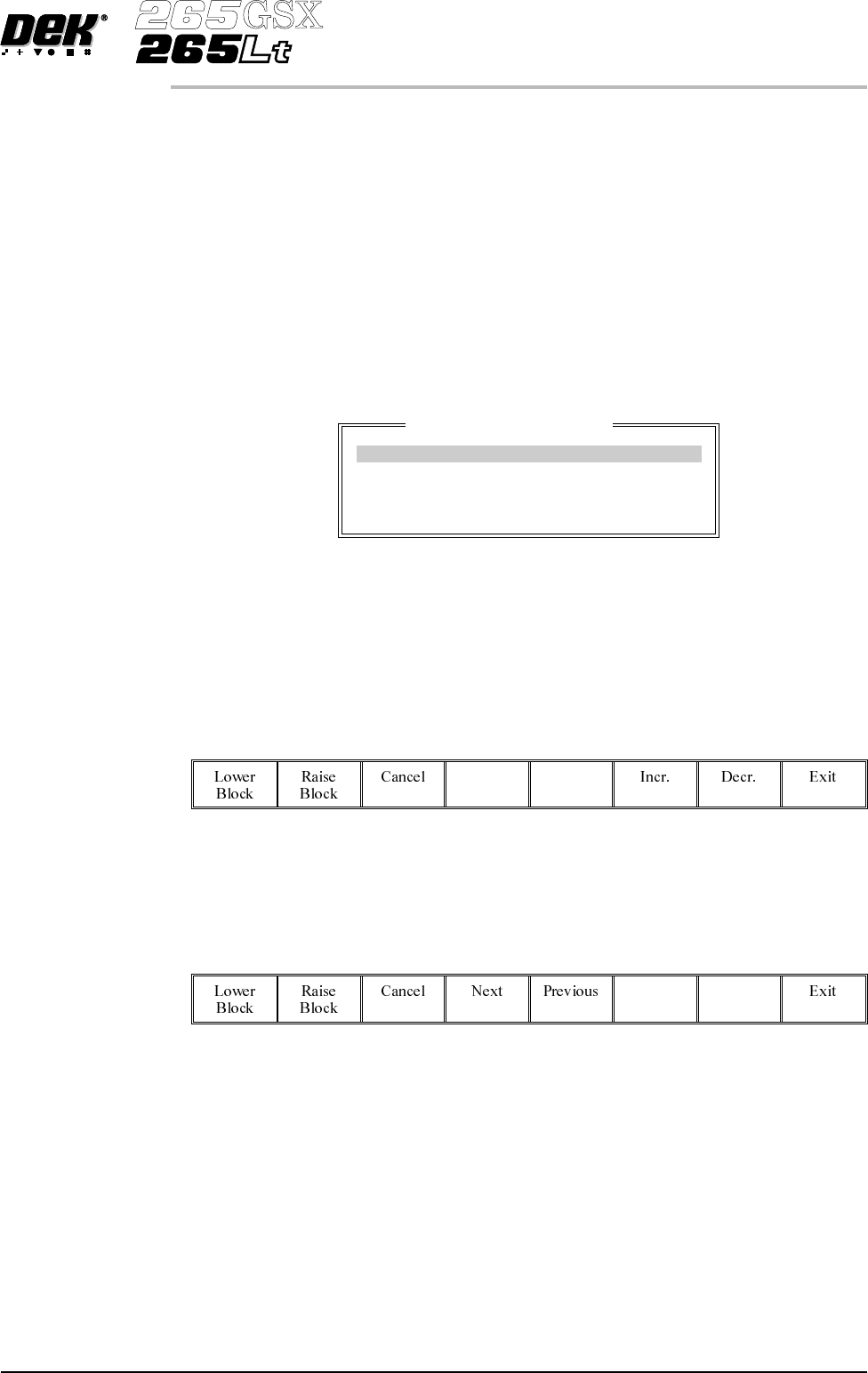
The Fine Pitch Block Control window is displayed:
NOTE
If Grid is selected under Autoflex Entry in Set Prefs, the parameter values are
column letters and row numbers not in mm as shown.
8.
Use the Next and Previous keys (F4 - F5), to highlight each parameter in
turn.
Next Previous
9. Either:
a.
Use the Incr. and Decr. keys (F6 - F7), to set each of the values.
Incr. Decr.
Or:
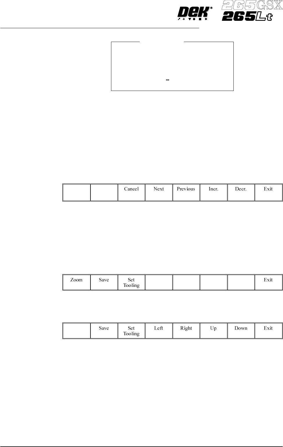
b. (i). Press the forward slash key (/) on the keyboard. A window is displayed
for the selected parameter:
Software Version 6 User Manual 1.61
MACHINE PROGRAMMING
STAGE 6F
Fine Pitch Block Control
Block Origin X 0.0 mm
Block Origin Y 0.0 mm
Block Final X 152.0 mm
Block Final Y 101.0 mm
(ii). Using the numeric keypad enter the new value.
(iii). Press Enter on the keyboard.
(iv). Repeat Steps 8, 9a or 9b for each parameter.
10.
Select either Lower Block (F1) or Raise Block (F2) as required.
Lower
Block
Raise
Block
11. Go to Step 27.
Toggling State of Individual Pins
12.
UsetheLeft,Right,UpandDownkeys(F4-F7),topositionthehighlighted
cursor over the required section.
Left Right Up Down
13.
Select Zoom (F1).
Zoom
1.62 User Manual Software Version 6
MACHINE PROGRAMMING
STAGE 6F
Block Origin X
Minimum Value 0.0000 mm
Maximum Value 152.0000 mm
Increment 0.5000 mm
Current Value 0.0000 mm
Enter New Value mm
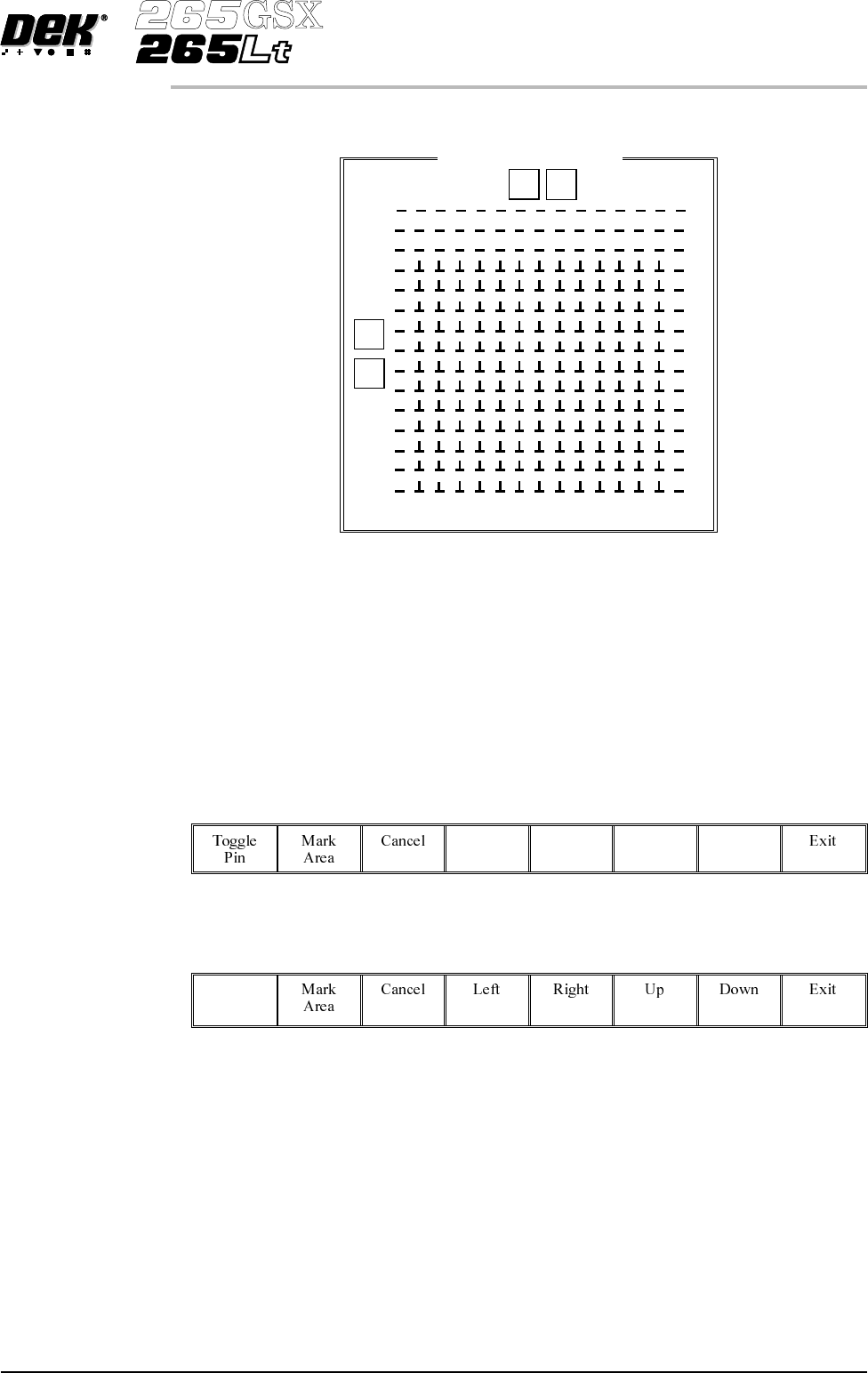
A close up view of the Fine Pitch Autoflex Matrix window is displayed:
NOTE
The figures down the right hand side of the template correspond to the figures on
the MMI matrix and represent the distance from the front edge of the board. The
figures across the top of the template are referenced to the centreline of the
board, where as the MMI matrix is referenced to the fiducial reference point on
the front edge of the board.
14.
Use the Left, Right, Up and Down keys (F4 - F7), to highlight the required
pin.
Left Right Up Down
15.
Select Toggle Pin (F1).
Toggle
Pin
16. Repeat Steps 14-15 for any other pins.
17. Go to Step 26.
Software Version 6 User Manual 1.63
MACHINE PROGRAMMING
STAGE 6F
Fine Pitch Autoflex Matrix
77.0
14.5
168.5
0 154
9
J
92.5