YG12F_Ope_E.pdf - 第126页
OPERA TOR’S MANUAL Oct. 2009 V ersion 1.00 © Y AMAHA MOTOR CO., L TD. IM Operations All rights reserved. No part of this publication may be reproduced in any form without the permission of Y AMAHA MO TOR CO., L TD. Infor…
A-1
Appendix
A1. Specifications
n
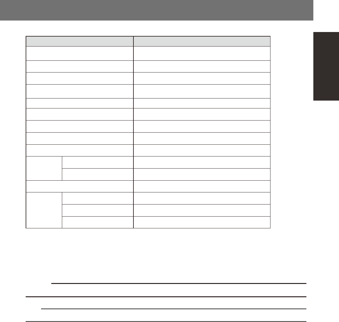
YG12F series specifications
Item Specifications
Operating ambient temperature
Function guaranteed: 15 to 35°C
Accuracy guaranteed: 20 to 28°C
Operating ambient humidity 20 to 90% (no condensation), optimal range: 50 to 60%
Noise level 78dB
Power requirement (voltage and frequency) 3-phase AC 200/208/220/240/380/400/416 V ± 10%, 50/60 Hz
Average power consumption 1.1kW
Power cable (conductor cross-section area) 3.5 mm
2
or more
Overvoltage category *
1
Category III
Pollution degree *
1
Degree 2
Supply air pressure *
2
0.60~0.70MPa
Air flow rate
YG12F 120Nl/min, Instantaneous maximum flow rate: 310Nl/min
YG12F+ATS15 130Nl/min, Instantaneous maximum flow rate: 320Nl/min
Board transport height *
3
900 mm ± 10 mm
Data
Number of mounting points *
4
10,000 points
Number of part types 255 types per board
Number of fiducial marks *
5
128 sets per board
*1: Conforms to IEC60664-1.
*2: Clean, dry air passed through an air dryer and filter.
*3: Distance from the floor surface to the upper surface of conveyor belt.
*4: Decreases with the number of boards, blocks and fiducial marks.
*5: When using 2-point fiducial mode.
c
Conveyor's board sensors may fail to detect a production board if it has a slit or cutout.
n
NOTE
For more detailed information not listed above, please refer to specification sheets.

S-1
Index
A
Alarm buzzer 1-2
ATS15 1-12
Axis configuration 1-16
Blow station 1-17
Board clamping method 2-23
Board production
Ending production 3-6
Pre-operation check 2-18
Resuming operation 3-4
Starting production 3-1
Starting the machine 2-19
C
Caution labels xv
CE marking i
Component supply section 1-11
Component trays 2-32
Connection between machines 1-2
Conveyor unit 1-15
Conveyor unit setup 2-23
Conveyor width 2-12
[Convey-out stop] button 3-6
[Cycle Stop] button 3-6
Data input unit 1-3
Dummy feeder iv
E
Emergency stop
Canceling emergency stop 2-1
Error
Clearing an error 2-2
Errors and troubleshooting 2-3
Feeder plates 1-11
Air connector 1-11
Power supply connector 1-11
Feeder setup section 1-11
Fixed 24-feeder plate 1-11
H
Head assembly 1-5
5-in-line multi-head assembly 1-6
K
Keyboard 1-3
Machine main unit 1-1
Names and functions of major parts 1-1
Manual feeder operation 2-15
Manual head operation 2-14
Manual I/O operation 2-16
[Monitor] button 3-8
Mouse 1-3
Multi-vision camera 1-6
N
Nozzle shaft blow 1-18
Nozzle station 1-9
Nozzle types 1-7
Narrow adjacent type 1-8
Standard type 1-7
One-stop cover iv
Operation panel 1-3
[READY] button 2-1
Operation panel buttons 1-4
[ACTIVE] button 1-4
[EMERGENCY STOP] button 1-4
[ERROR CLEAR] button 1-4
[READY] button 1-4
[RESET] button 1-4
[START] button 1-4
[STOP] button 1-4
Operation screen 2-8
Menu button area 2-8
Status area 2-8
Operation speed 3-3
[Operator] button 2-20
P
Pallet 1-13
Setting a pallet 2-33
Password 2-20
Pick Rate Warning 3-22
Pickup position offset 3-20
Power switch 1-2,2-19
Turning power off 3-6
Pressure gauge 1-2
Production monitors 3-8
Push-up pin 2-25
Q
QFP dump station 1-23
R
Recognition system 1-15
Return-to-origin 2-19
S
Safety ii
Safety cover 1-2
Safety message vi
Setup screen 2-11
[Check Nozzles] button 3-3
[Feed Bulk] button 3-3
[Required Nozzles] button 3-3
[Required Parts] button 3-2
Signal light 1-2
Specifications A-1
T
Tape feeder
Operation check 2-37
Settings on the mounter side 2-34
Setting the tape 2-26
Tray changer 1-12
Tray components 2-32
U
Unit screen 2-12
W
Warming up 2-21
[Warm Up] button 2-21
Warning labels x
"watch-and-wait" mode 3-24

OPERATOR’S MANUAL
Oct. 2009
Version 1.00
© YAMAHA MOTOR CO., LTD. IM Operations
All rights reserved. No part of this publication may be
reproduced in any form without the permission of
YAMAHA MOTOR CO., LTD.
Information furnished by YAMAHA in this manual is believed to
be reliable. However, no responsibility is assumed for possible
inaccuracies or omissions. If you find any part unclear in this manual,
please contact YAMAHA or YAMAHA sales representatives.