YG12F_Ope_E.pdf - 第44页
1-10 1 Part names and functions Front of machine HEAD 1 TYPE31 1A HEAD 2 TYPE31 1A HEAD 3 TYPE31 1A HEAD 4 TYPE31 1A HEAD 5 TYPE31 1A HEAD 1 TYPE312A HEAD 2 TYPE312A HEAD 3 TYPE312A HEAD 4 TYPE312A HEAD 5 TYPE312A HEAD 1…
1-9
1
Part names and functions
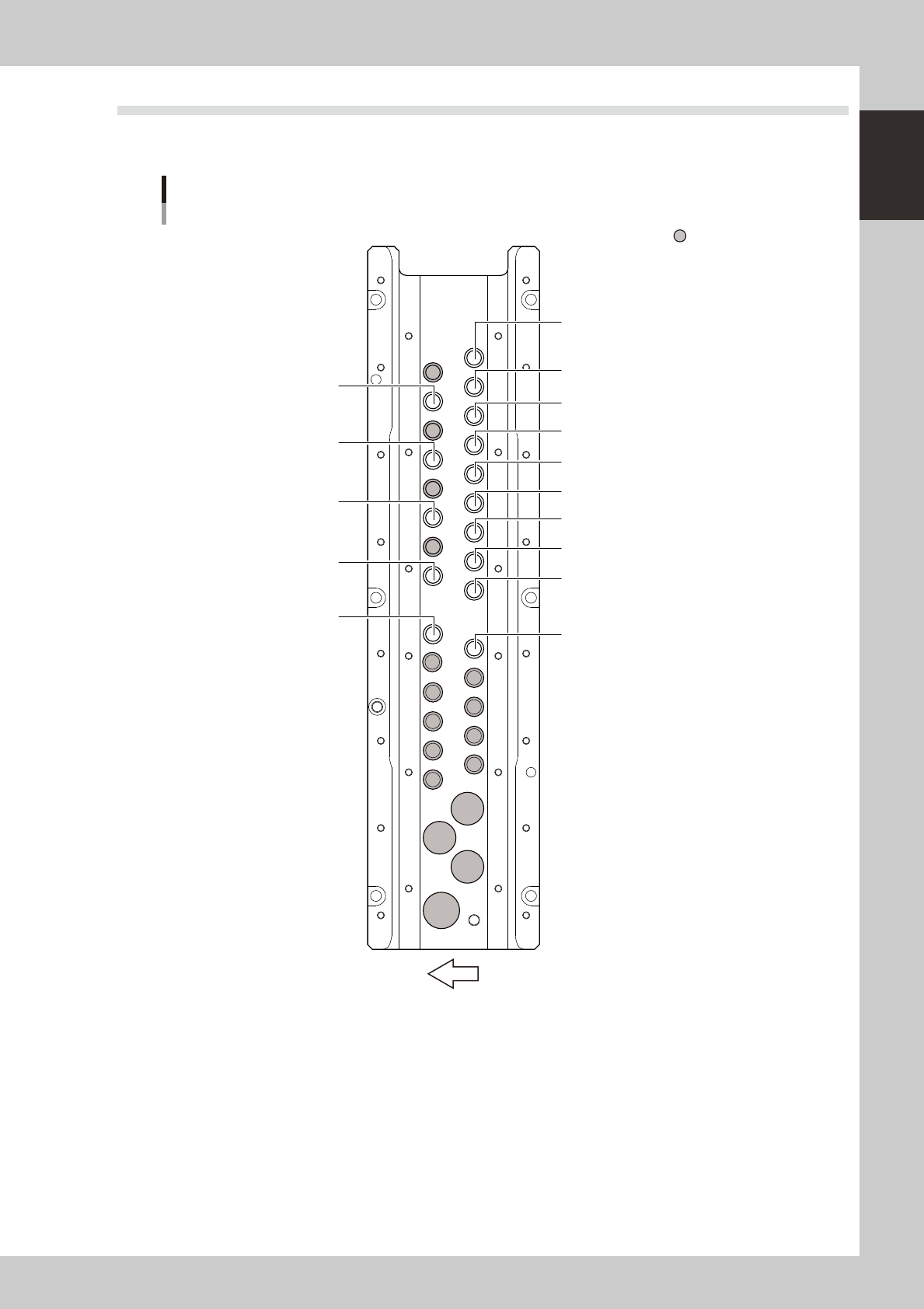
3.3 Nozzle station (option)
The nozzle station accommodates various nozzles for automatic change.
The drawings below show the nozzle station No. and the allotted head No. and mating nozzle type.
HEAD 1
TYPE301A
HEAD 1
TYPE303A
HEAD 3
TYPE303A
HEAD 2
TYPE304A
HEAD 5
TYPE304A
HEAD 4
TYPE303A
HEAD 2
TYPE301A
HEAD 3
TYPE301A
HEAD 4
TYPE301A
HEAD 5
TYPE301A
HEAD 1
TYPE302A
HEAD 2
TYPE302A
HEAD 3
TYPE302A
HEAD 4
TYPE302A
HEAD 5
TYPE302A
Front of machine
Nozzle station
Standard type
Custom nozzle pockets
23107-M7-00
1-10
1
Part names and functions
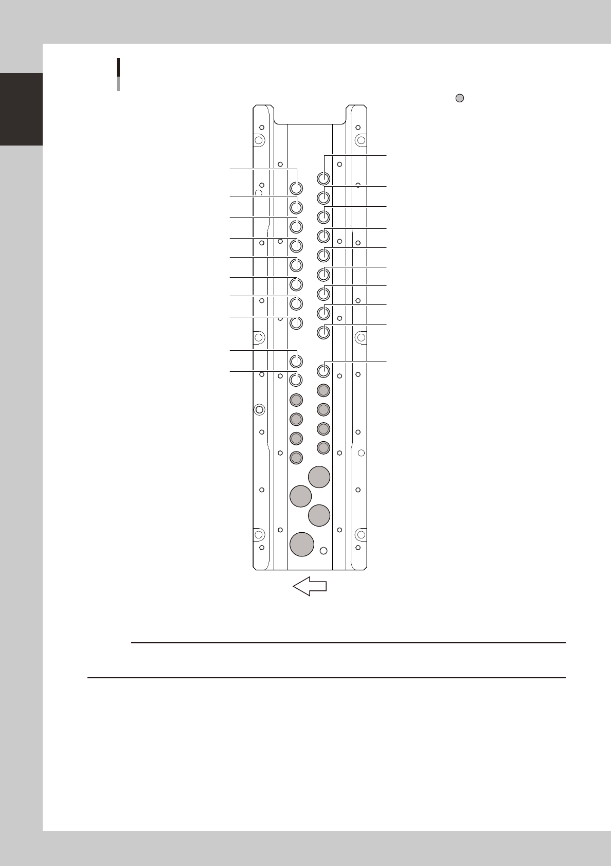
Front of machine
HEAD 1
TYPE311A
HEAD 2
TYPE311A
HEAD 3
TYPE311A
HEAD 4
TYPE311A
HEAD 5
TYPE311A
HEAD 1
TYPE312A
HEAD 2
TYPE312A
HEAD 3
TYPE312A
HEAD 4
TYPE312A
HEAD 5
TYPE312A
HEAD 1
TYPE314A
HEAD 3
TYPE314A
HEAD 4
TYPE314A
HEAD 2
TYPE315A
HEAD 5
TYPE315A
HEAD 1
TYPE313A
HEAD 2
TYPE313A
HEAD 3
TYPE313A
HEAD 4
TYPE313A
HEAD 5
TYPE313A
Nozzle station
Narrow adjacent type
Custom nozzle pockets
23108-M7-00
c
restrictions on the size of components suitable for those nozzles.
1-11
1
Part names and functions
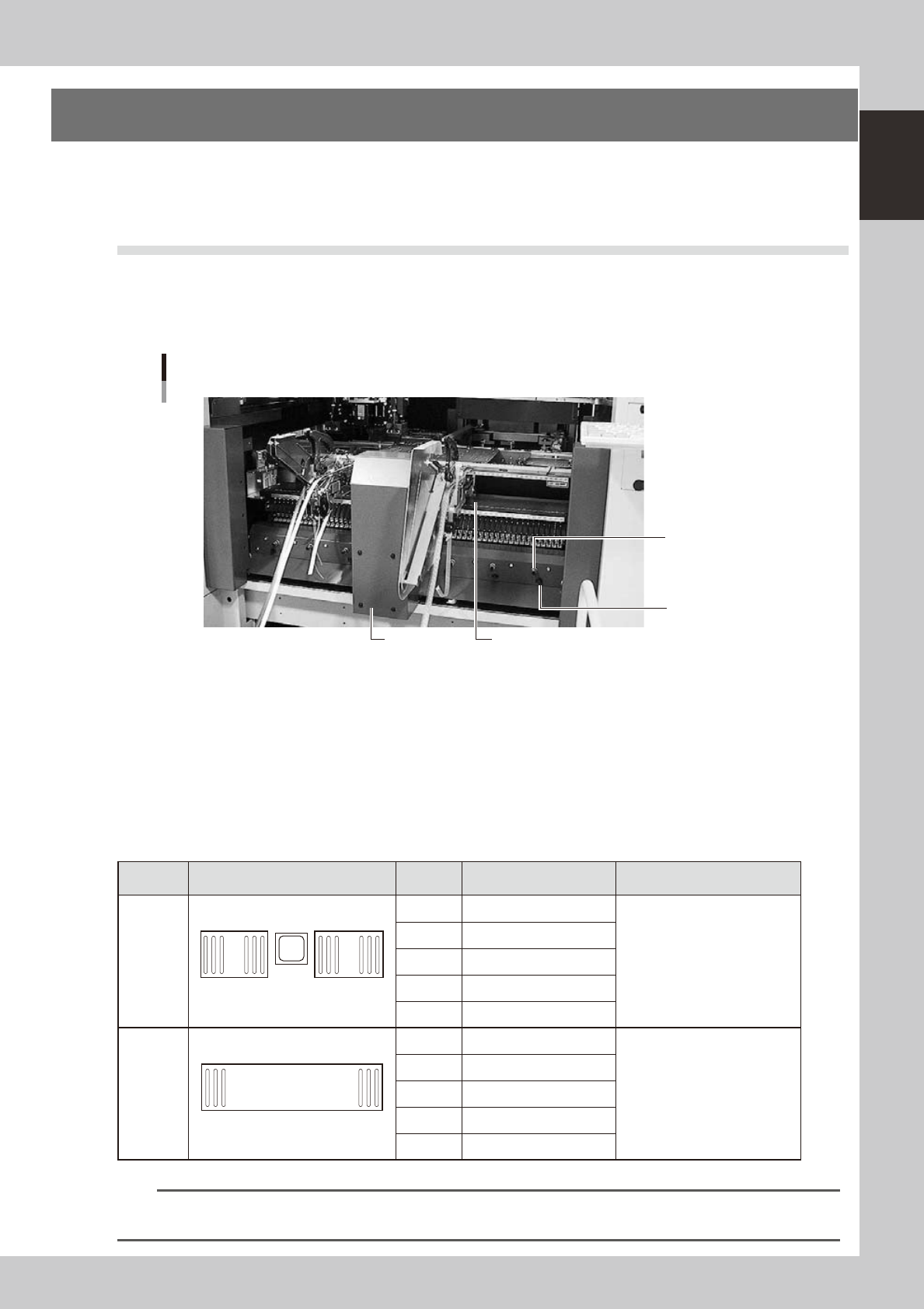
4. Component supply section
The feeder setup section is equipped with feeder plates for installing feeders such as tape feeders, and power
supply connectors and air connectors for driving optional units. Automatic tray changer (ATS15) is available
for YG12F as an option.
4.1 Supplying components from feeder plates
The tape feeder is installed on the feeder plate and is driven by air pressure supplied from the mounter.
4.1.1 Fixed 24-feeder plate
Feeder plate section
Safety cover
Air connector
Power supply
connector
24-feeder plate
23109-M7-00
Power supply connector
When using optional units such as dump stations, plug the power cord into these connectors.
Air connector
Use these air connectors when using an optional device such as an air blow gun. Connect the air tube (outer diameter
4mm) to supply compressed air to the optional device from the mounter.
■
Head No. and feeder set No.
Some feeders cannot be reached by a head depending on the head assembly configuration and X-axis movement range.
The tables below show feeder set numbers that can be accessed by each head of the machine.
Type Layout Head No. Accessible feeder set No.
Number of feeders than can be
attached
Front
24-feeder
plate
(fixed) × 2
1
24
25
48
1 9 to 48
48 when FT feeders are used
2 7 to 46
3 5 to 44
4 3 to 42
5 1 to 40
Front
60-feeder
plate
(fixed)
1 60
1 101 to 151
59 when FT feeders are used
2 103 to 153
3 105 to 155
4 107 to 157
5 109 to 159
n
NOTE
Accessible feeder positions may differ from the above when the Feeder Definition parameter in component
information is set to "Teach" or "Relative".