YG12F_Ope_E.pdf - 第56页
1-22 1 Part names and functions 3 A confirmation dialog box appears asking y ou to make a final check. Check the contents of the dialog box and pr ess the corresponding button. [OK] : Per forms nozzle shaft blow to clean…
1-21
1
Part names and functions
n
When the machine has a nozzle station (option)
When the settings are made so that all nozzles can be changed using a nozzle station (option), follow these steps.
1
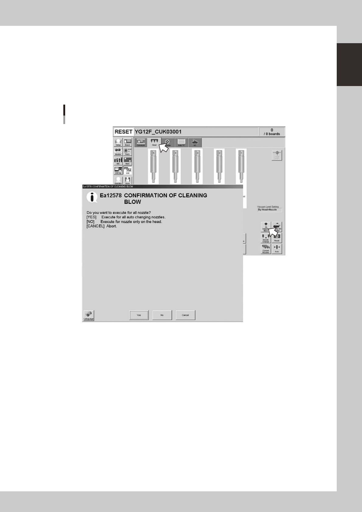
Open the [Unit] – [Head] screen.
2
Press the [Cleaning Blow] button.
A confirmation dialog box appears asking whether to perform nozzle shaft blow.
Press the [OK] button to perform nozzle shaft blow and proceed to the next step. If you want to cancel
nozzle shaft blow, press the [Cancel] button.
Nozzle shaft blow
When nozzle station (option) is used
24103-M7-00
1-22
1
Part names and functions
3
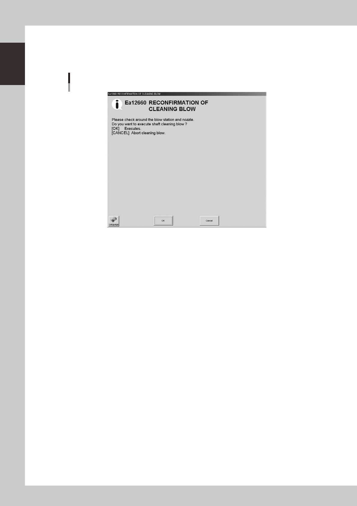
A confirmation dialog box appears asking you to make a final check.
Check the contents of the dialog box and press the corresponding button.
[OK] : Performs nozzle shaft blow to clean the nozzles.
[CANCEL] :
Closes the dialog box and returns to the [Unit]-[Head] screen without performing nozzle shaft blow.
Final confirmation dialog box for nozzle shaft blow
24104-M7-00
n
Safety checks
The nozzle shaft blow function also contains the following safety checks.
• Nozzle shaft blow interruption alarm
The head immediately rises if operation stops during nozzle shaft blow due to emergency stop or an interlock triggering.
If the head rises but the air blow still continues, then the nozzle might come loose from the head. To prevent this, a
confirmation dialog box appears if the machine operation stopped during nozzle shaft blow.
• Nozzle sensors to check whether a nozzle is left on the blow station
The nozzle shaft blow function forces high-pressure air through the nozzles during cleaning, so the nozzles might come
loose from the head if machine operation stops during nozzle blow. If a nozzle comes loose from the head and remains
on the blow station while the automatic operation still continues, then the nozzle left on the blow station might interfere
with other heads or with the multi-max unit. To prevent this, nozzle sensors are installed so that the machine constantly
monitors whether a nozzle is left on the blow station.
An “interlock error” is issued if any of these sensors detects a nozzle on the blow station at any time other than when the
head is lowered during nozzle blow. The machine operation is then disabled.
1-23
1
Part names and functions
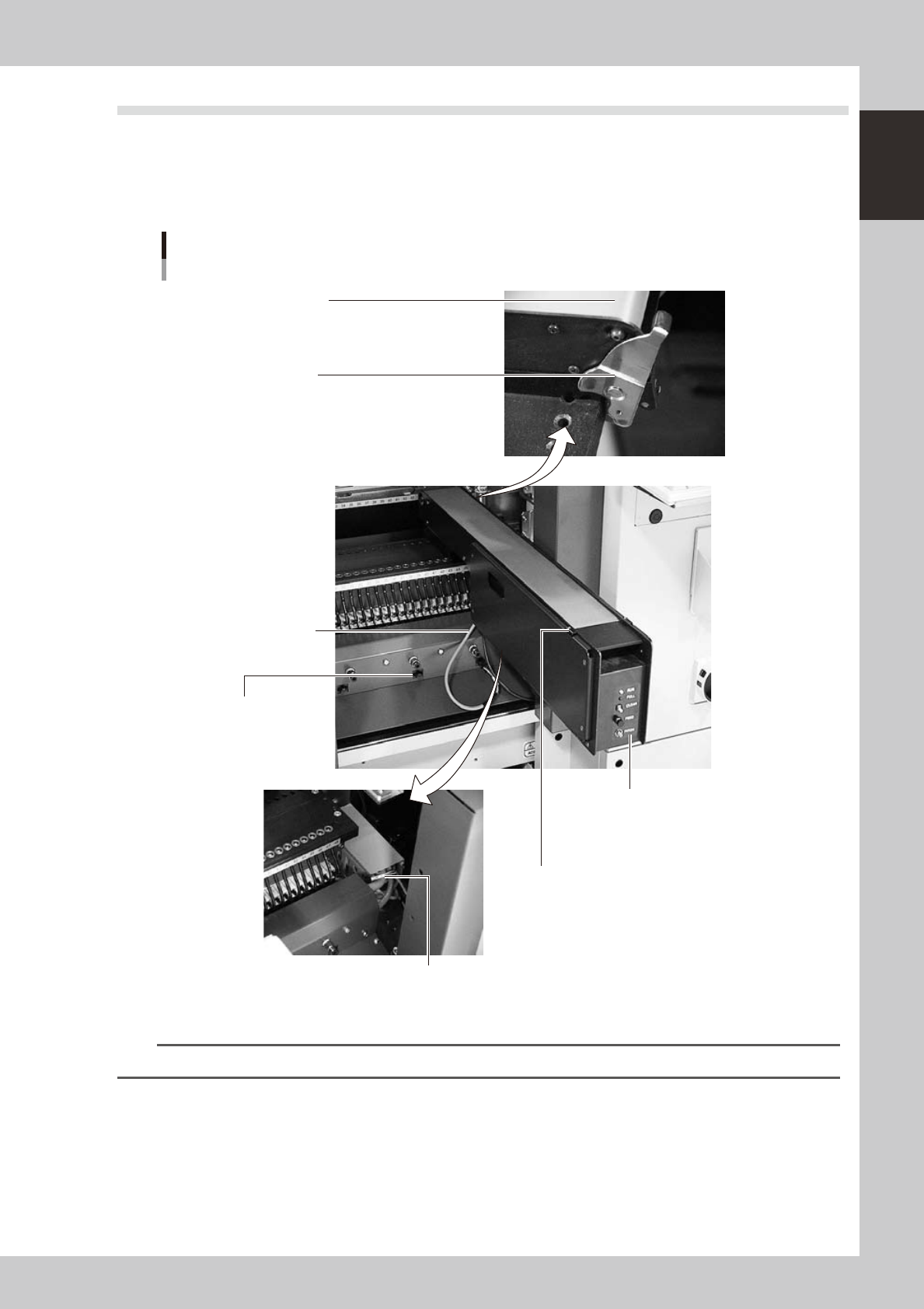
7.2 QFP dump station
If a QFP is judged defective by vision camera recognition, that QFP is temporarily placed on this dump station
without being damaged. The QFP placed on the dump station is then conveyed back at a specified feed pitch.
When the dump station becomes full, the memory counter or overflow sensor detects it and displays an error
message before the next defective QFP is returned to the dump station.
Photographs below show major parts and functions of the dump station.
Conveyor belt
The belt is used to transfer dumped components.
Clamp lever
Secures the machine to the feeder plate.
Dump harness (signal cable)
Harness for signal of dump station.
Feeder connector
(power supply cable)
Connector for power supply of
dump station.
Manual operation panel
Sets up status indication, pitch feed,
count clear feed pitch.
Overflow sensor (option)
Detects a dumped component transferred
with a transfer belt to this position to show
an error message.
Dump connector
Connector for connecting the dump harness.
Part names and functions
23117-M7-00
n
NOTE
Refer to option manual for details of how to use a QFP dump station.