YG12F_Ope_E.pdf - 第73页
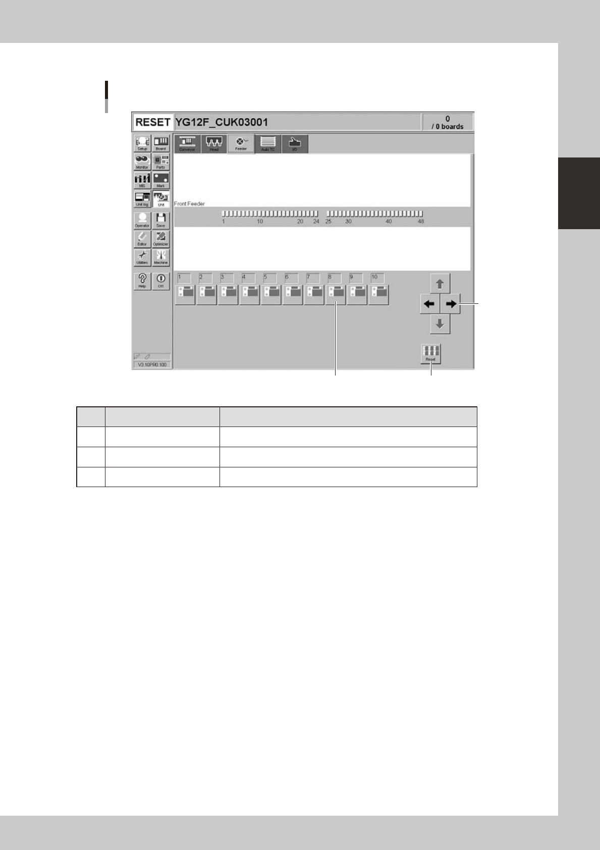
2-15 2 asic operation n Manual feeder operation [Unit] – [Feeder] screen 1 3 3 24210-M7-00 Button name Function 1 Right/left arrows Scrolls through the drive valve number display . 2 Drive valve T urns the feeder shutt…
2-14
2
asic operation
n
Manual head operation
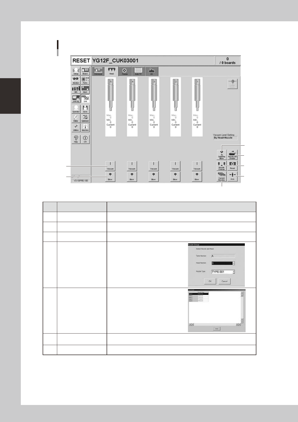
[Unit] – [Head] screen
1
2
3
4
5
6
7
24207-M7-00
Button name Function
1 Vacuum Turns the vacuum of each head on or off.
2 Blow Turns the air blow in each head on or off.
3 Nozzle STN Shutter Opens or closes the nozzle station shutter.
4 Nozzle Change
Opens the "Nozzle Change" dialog box.
Specify the head and nozzle type to
perform nozzle change.
5 Current Nozzles
Shows a list of nozzle types currently
attached to each head.
6 Axis
Opens the "Move Axis" screen. This is the same as the [Axis] button on the [Unit]-
[Conveyor] screen.
7 Cleaning Blow Not currently used.
2-15
2
asic operation
n
Manual feeder operation
[Unit] – [Feeder] screen
1
3
3
24210-M7-00
Button name Function
1 Right/left arrows Scrolls through the drive valve number display.
2 Drive valve Turns the feeder shutter drive valve on or off.
3 Reset Turns off all drive valves at a time.
2-16
2
asic operation
n
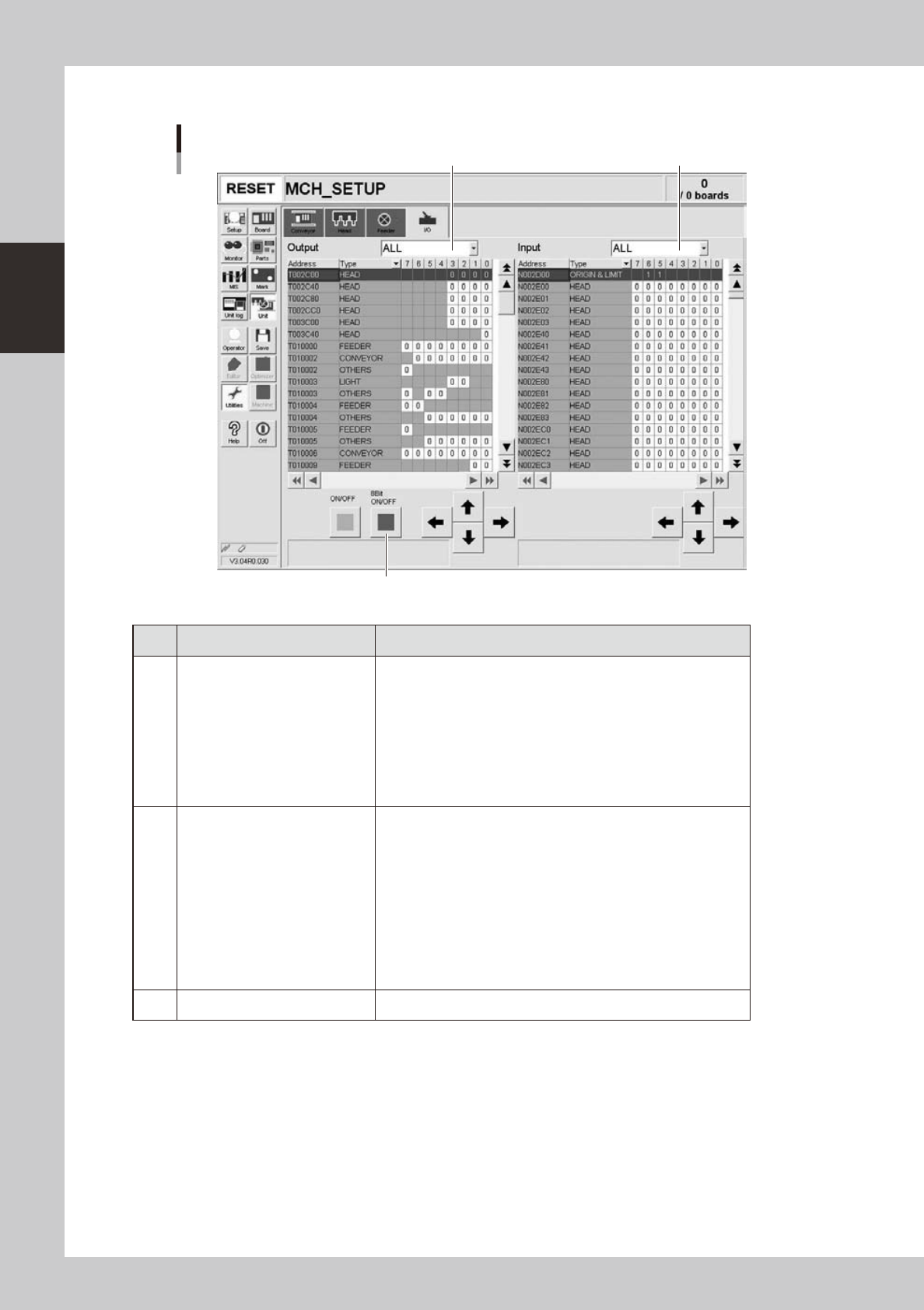
Manual I/O operation
[Unit] – [I/O] screen
1 2
3
24211-M7-00
Button name Function
1 Select output display group
Select the output group for display in the "Output" status list. The
following groups can be selected:
• ALL
• NSTA (nozzle station)
• LIGHT
• CONV (conveyor)
• HEAD
• BSTA (blow station)
• OTHERS
2 Select input display group
Select the input group for display in the "Input" status list. The
following groups can be selected:
• INTLCK (interlock)
• SRV (servo origin limit)
• FDR (feeder)
• NSTA (nozzle station)
• CONV (conveyor)
• LIGHT
• HEAD
• BSTA (blow station)
• OTHERS
3 ON/OFF Turns the selected valve on or off.