YG12F_Ope_E.pdf - 第85页
2-27 2 asic operation 4 Lift the tape guide. Hold down the front side restraint lev er and lift the tape guide. T ape guideT ape T ape guide Front side restraint lever 23207-M7-00 5 Set the tape in the tape feeder . Pa…
2-26
2
asic operation
4. Preparing the component supply unit
4.1 Tape feeder
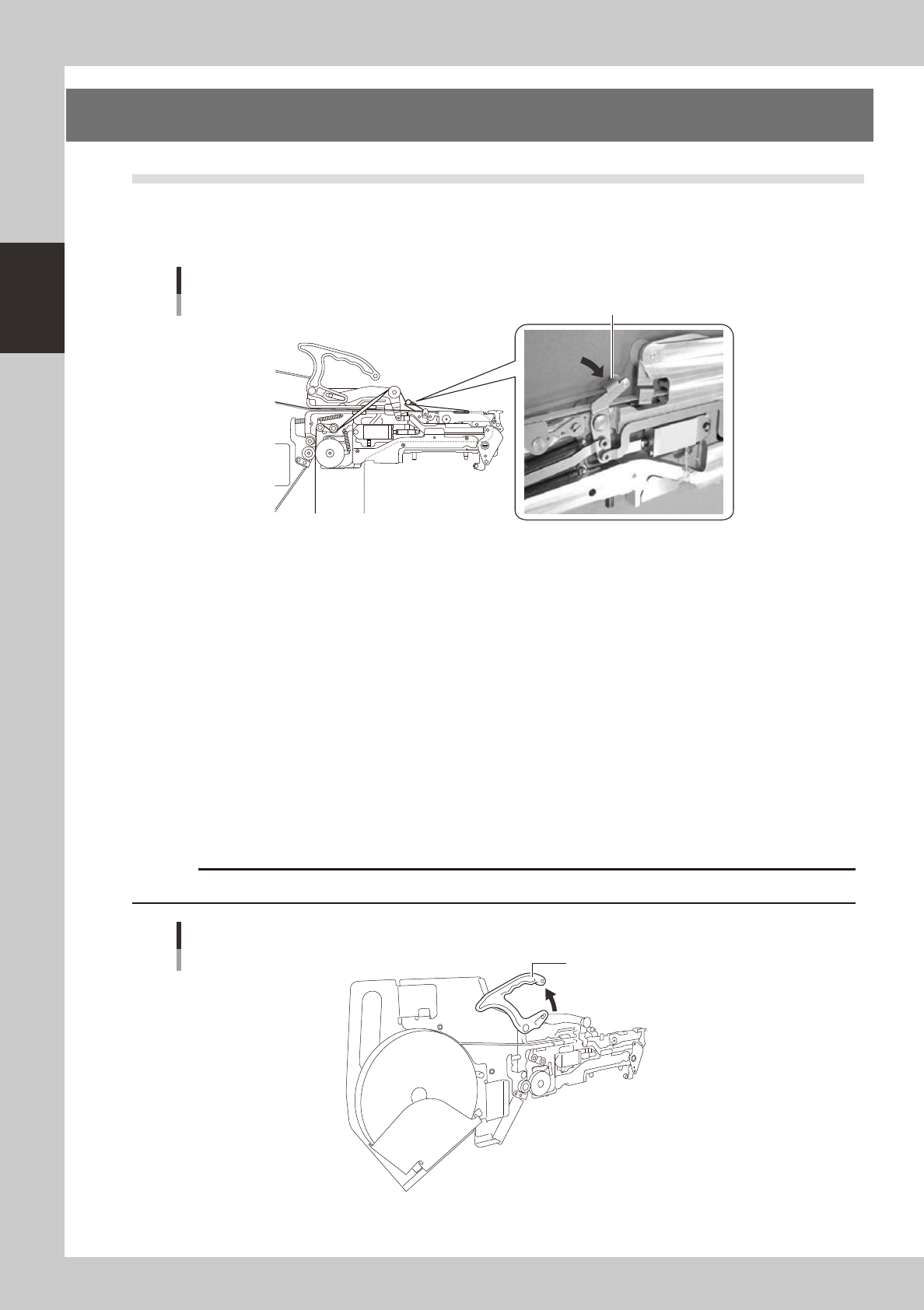
1. Checking the feed pitch and action
Press the Cover tape peeling lever to make sure that the tape is fed at a proper pitch.
Tape guide setup
Cover tape peeling lever
23205-M7-00
2. Setting the tape
When fitting a new roll of tape to a tape feeder, set the tape with the procedure below.
1
Peel off the top tape.
Tape consists of two layers: "carrier tape" that contains electronic components in the pockets and "top
tape" that covers the upper side of components on the carrier tape. Peel off the top tape to separate
these two layers.
2
Pull out the tape.
• InsertthereelinthepocketofthereelholderandpulloutthetapeincaseofFSorFS2(7inch).
• SetthereeltothereelaxisandthenpresswiththetensionleverincaseofFS2(15inch).
• RemovethereelhookbartoengagethemiddleholeoftapereelincaseofinstallingtoFT.
3
Lift the clamping lever lock handle.
Lift the clamping lever lock handle to lift the tape guide.
c
Clamping lever lock handle
Clamping lever lock handle
23206-M7-00
2-27
2
asic operation
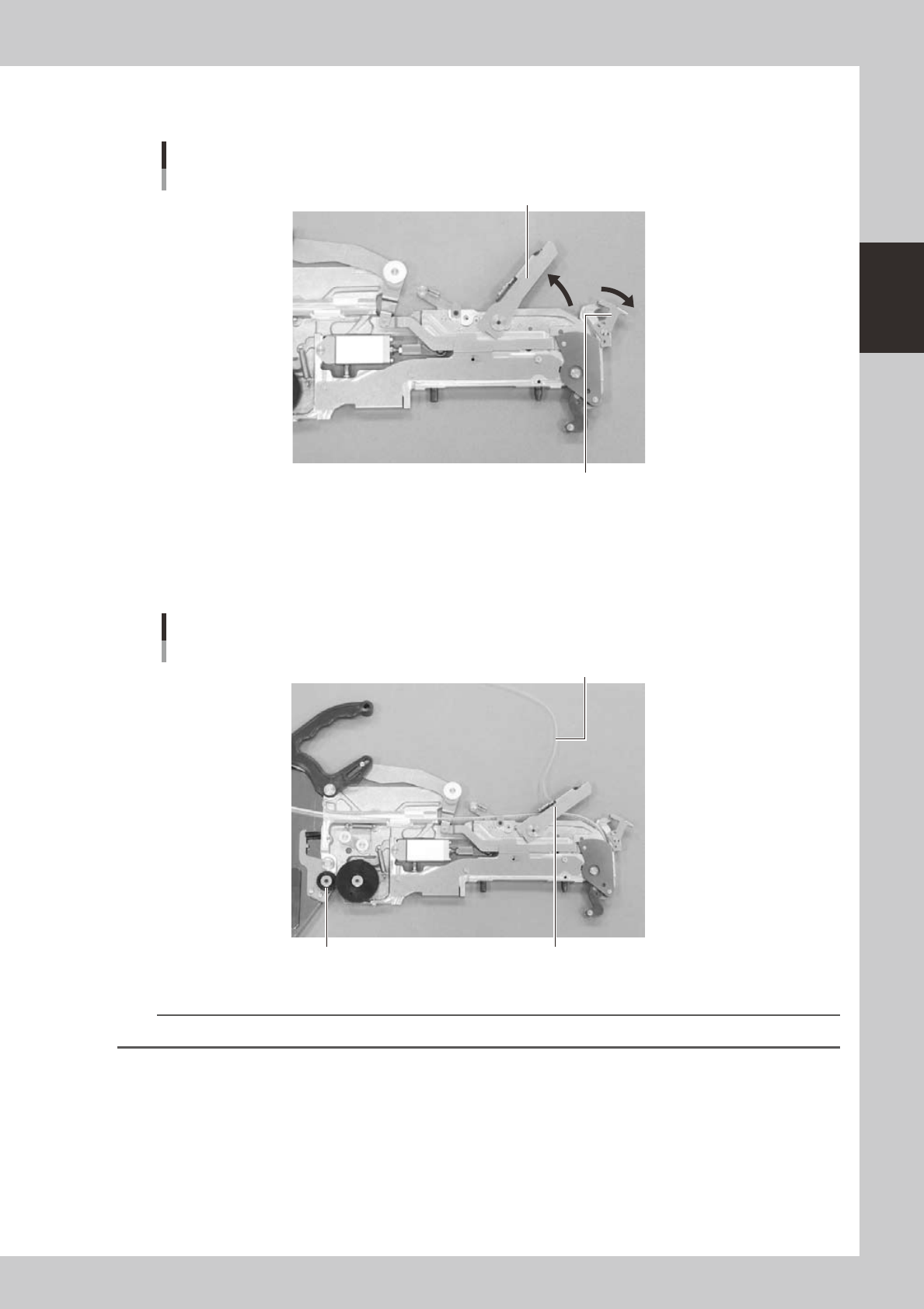
4
Lift the tape guide.
Hold down the front side restraint lever and lift the tape guide.
Tape guideTape
Tape guide
Front side restraint lever
23207-M7-00
5
Set the tape in the tape feeder.
Pass the tape through the groove.
Pull out some portion of the tape beforehand so that the top tape can reach the idle roller assembly.
Pass the top tape through the notch of the tape guide and fold it back.
Setting the top tape
Top tape
Tape guide notch
Idle roller assembly
23208-M7-00
n
NOTE
“Feeder User’s Manual” explains how to set a tape in details.
2-28
2
asic operation
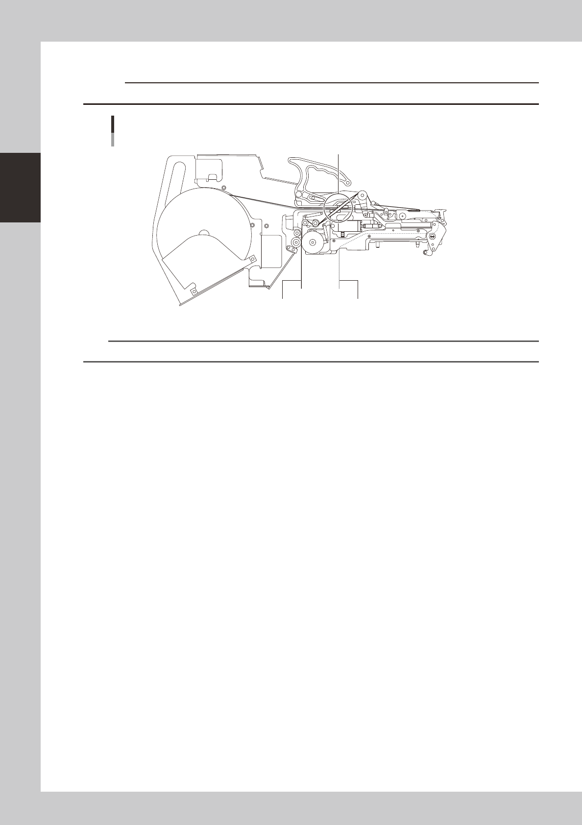
Route the tape to the path described below.
c
Tape path drawing
Carrier tape
Portion AA
Top tape
E
A – E : Top tap
a – c : Carrier tape
A
a
c
C
B
b
D
D
In case of FS2
23209-M7-00
n
NOTE
Tape path of FT and that of FS2 are the same.
6
Transfer components to the pickup position.
When the tape is set, press the bend portion of the cover tape peeling lever to transfer components to
the pickup position.