YG12F_Ope_E.pdf - 第89页
2-31 2 asic operation 6 Push do wn the clamping lever a wa y from you. Lower the clamping lever lock handle. Push down the clamping lever until it is securely set on the feeder plate. If the lever is not properly set, …
2-30
2
asic operation
4
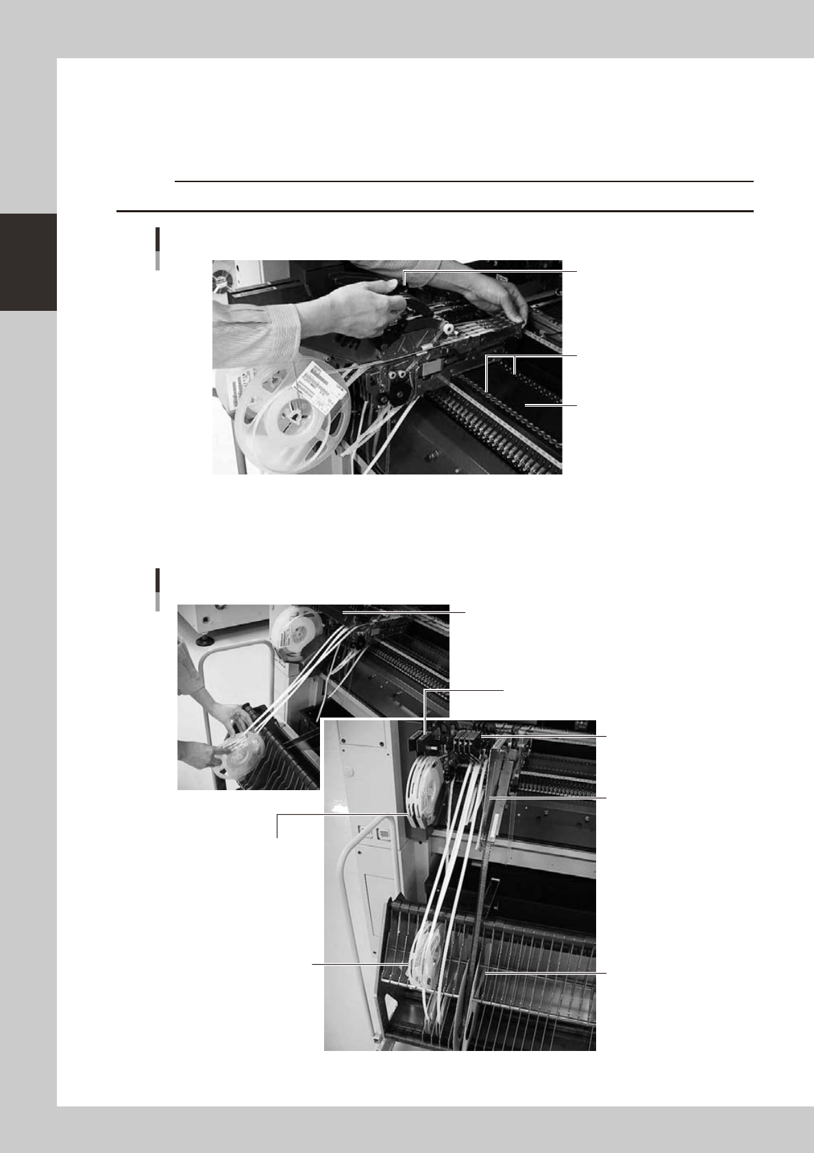
Insert the feeder unit into the knock-pin holes on the feeder plate.
Hold the edge of the feeder and the clamping lever lock handle while the handle is in the lifted position,
and lower the feeder from directly above the feeder plate. The feeder plate has knock-pin holes for
front knock-pin and rear knock-pin of the feeder. Insert the front- and the rear-knock pins on the feeder
into the knock-pin holes securely.
c
Installing the feeder
Knock-pin holes
Feeder plate
Handle
23211-M7-00
5
Set the tape reel to the reel holder.
The reel holder pocket can contain one tape reel. Make sure to use upper and lower steps in staggered
arrangement to locate feeders closely together.
Setting the tape reel
Store the reel hook bar.
FS2 type
8 mm feeder
CL type
Large-size feeder
Store a large-size
reel here
It is impossible to locate 12mm pitch
feeders closely together
Use upper and lower steps in
staggered arrangement
FT type
8 mm feeder
23212-M7-00
2-31
2
asic operation
6
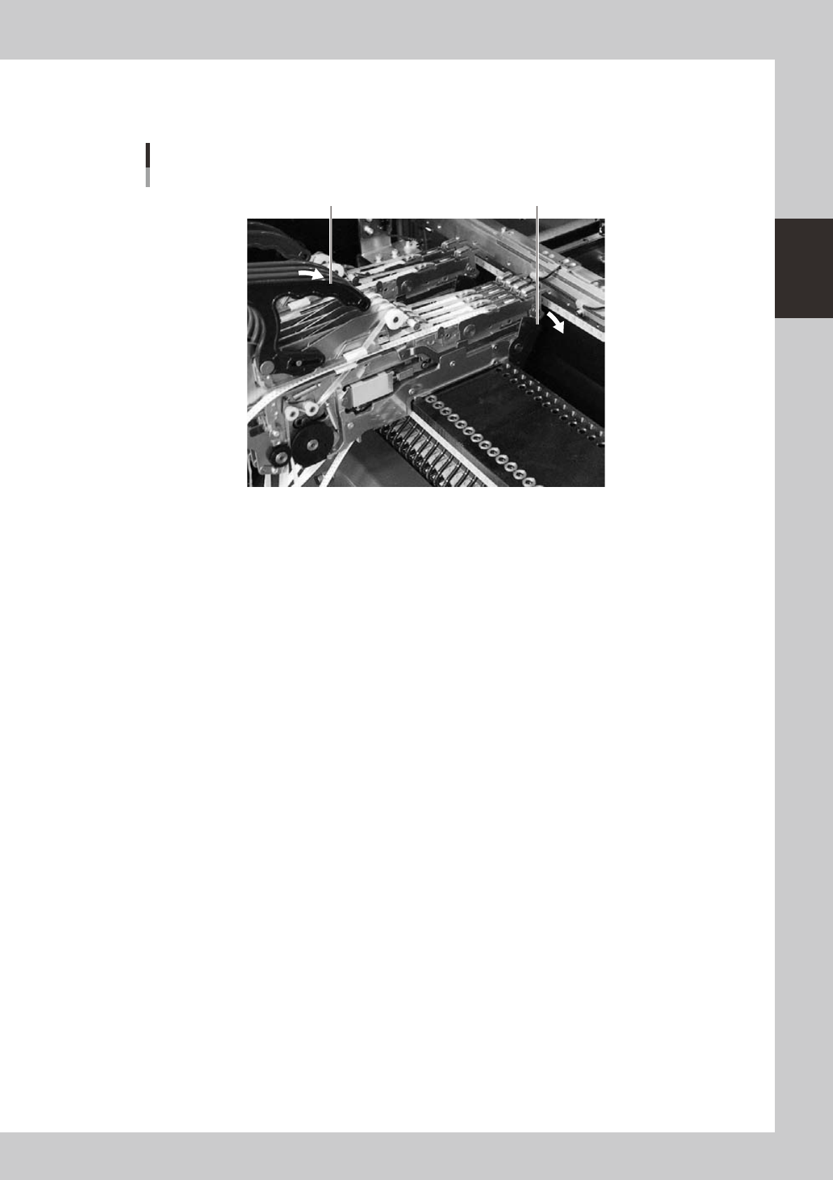
Push down the clamping lever away from you.
Lower the clamping lever lock handle. Push down the clamping lever until it is securely set on the feeder
plate. If the lever is not properly set, the feeder may come off during mounting or operation.
Clamping Lever
Clamping lever lock handle Clamping lever
23217-M7-00
2-32
2
asic operation
4.2 Setting the tray components
n
Precautions when handling pallets
Observe the following points when handling the pallets.
• Store the pallets in a clean environment where dust, grime and oil will not adhere.
• Take care not to drop the pallets or apply excessive force or impacts. Do not use a pallet if it is warped or deformed
after having been dropped.
• Avoid hurting yourself on the edges of the pallets.
4.2.1 Setting the component trays in the pallet
Several component trays can be set on one pallet (depending on the size of trays). Set the trays as described
below.
Clamping the component tray
Using one tray
Using several trays
Tray pitch X
Clamping magnet
Tray
Tray pitch Y
Pallet reference position (pallet origin position)
23213-M7-00
1
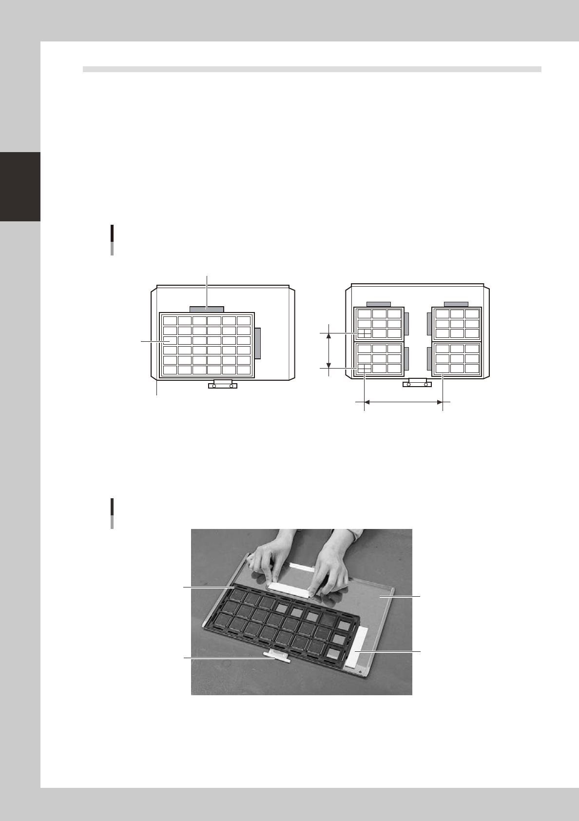
Remove the tray clamp magnets.
2
Set the component tray on the pallet.
Set so the corner of the component tray is aligned with the pallet reference position (pallet origin
position). After setting the tray, clamp it in place with the magnets.
Clamping the component tray
Pallet pullout piece
Tray clamp magnet
Pallet
Tray
23214-M7-00
3
Check that the component tray is clamped.
Press on the tray to make sure it is securely clamped by the magnet.