CP-6-series Mechanical Reference.pdf - 第133页
Part 3 Chapter 3 Replacing Consumable Parts Edition 1.6 3-3-2 CP-6-series Mechanical Reference 0603 and 1005 Nozzles for the CP-6 Series The standard nozzles for 0603 and 1005 parts are pipe-shaped and will bend relative…
Part 3 Chapter 3 Replacing Consumable Parts
Edition 1.6 3-3-1 CP-6-series Mechanical Reference
3. Replacing Consumable Parts
3.1 Nozzle Replacement
Point
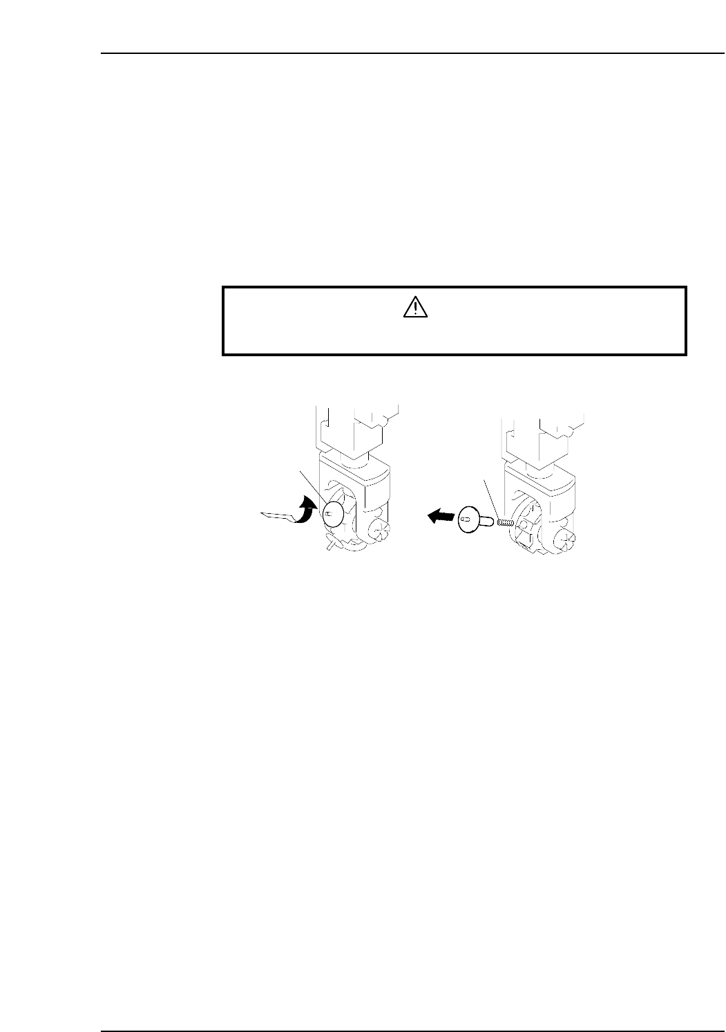
Replace nozzles that become bent, deformed, or blocked. When removing the damaged
nozzle, be careful not to lose the spring loaded under it.
Procedure
Warning
Turn off the 200 V servo power before carrying out this work.
Nozzle
Spring
Push and turn
Remove slowly
CP6M3055
Part 3 Chapter 3 Replacing Consumable Parts
Edition 1.6 3-3-2 CP-6-series Mechanical Reference
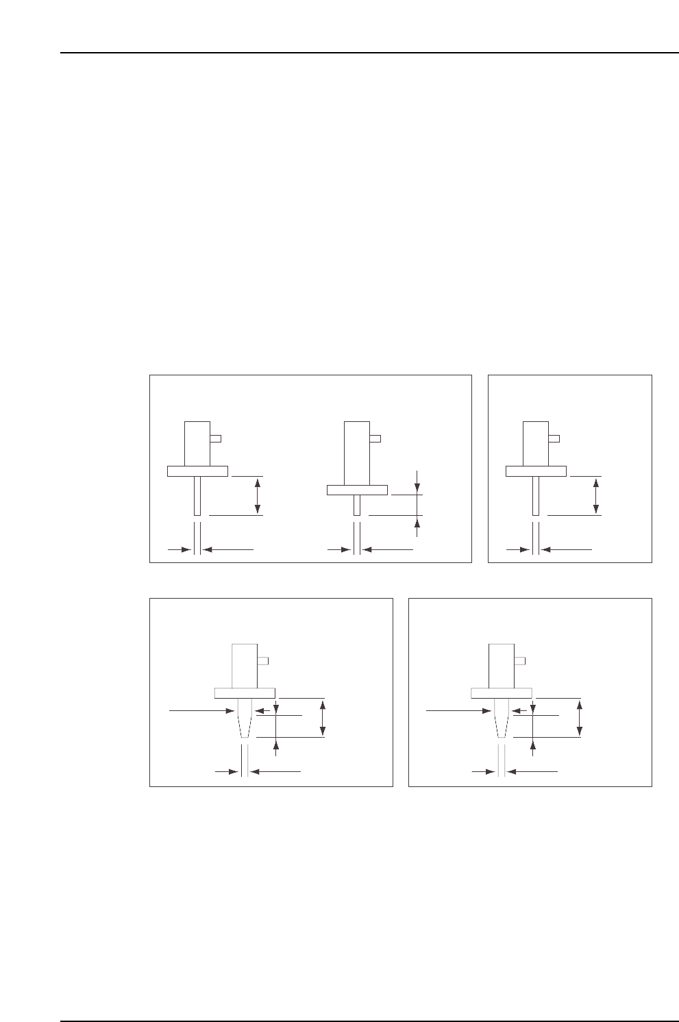
0603 and 1005 Nozzles for the CP-6 Series
The standard nozzles for 0603 and 1005 parts are pipe-shaped and will bend relatively
easily when touched. A 0.4-mm nozzle with a short pipe section is available to reduce
bending, and durable tapered nozzles are also available.
Please consider the following points when ordering nozzles for 0603 and 1005 parts.
1. Tapered nozzles are optional and must be requested specifically.
2. When using tapered nozzles, the nozzle shape entails certain limitations of prior
part placements.
3. The 0603 tapered nozzles are only compatible with the CP-642/642M/642ME, CP-
643/643M/643ME, and CP-65/65E.
Ø0.4
6.5 mm
Ø0.4
AWPH970✽
Ø0.97
6.5 mm
3.5 mm
AWPH972✽
Ø0.7
Ø1.27
6.5 mm
3.5 mm
AWPH973✽
CP6MR008
6.5 mm
Ø0.7
AWPH951✽
4.5 mm
Ø0.4
AWPH971✽
0603 pipe-shaped nozzle 1005 pipe-shaped nozzle
0603 tapered nozzle 1005 tapered nozzle
Part 3 Chapter 3 Replacing Consumable Parts
Edition 1.6 3-3-3 CP-6-series Mechanical Reference
3.2 Nozzle Reflective Disk Replacement
Point
Replace the nozzle fluorescent seal if the seal becomes dirty and causes vision processing
errors.
Procedure
1. Always wash your hands before handling the seals.
2. Choose the correct disk, referring to table below if necessary.
3. Check that the fluorescent disk is free of deformity and is clean.
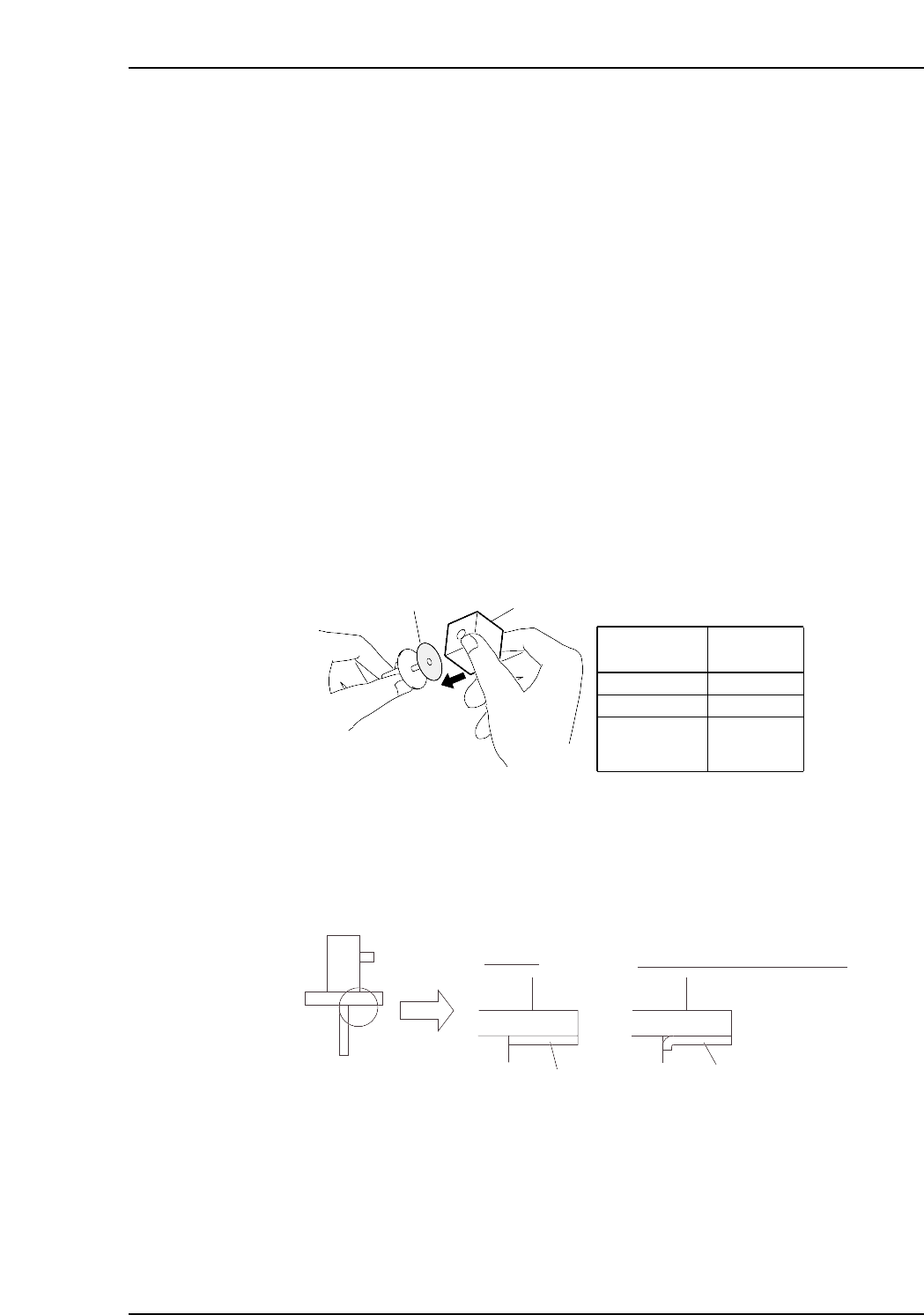
4. Peel the fluorescent disk from its paper backing and remove the small circular
cutout at the center of the seal by pushing it out from the side of the seal covered
with fluorescent paint. If the cutout is pushed out from the side covered with
adhesive, some of the fluorescent paint may be torn away when the circular cutout
comes loose from the rest of the disk.
5. Match the center of the disk with the center of the nozzle. Using jig (for reflective
plate), push the disk into the nozzle as shown in figure below. Check that no
space exists between the seal and the nozzle.
6. Use a utility knife to cut away any excess fluorescent seal.
7. Clean the fluorescent seal with a soft brush.
Note: Always use the jig because the fluorescent seal must be flat and centered on the disk.
Vision processing errors may occur if the inner edge of the seal contacts the pipe, if the seal
is torn, or if the seal hole does not line up with the pipe.
CP6MR009
Fluorescent seal
Fluorescent seal
Nozzle
Expanded view
Correct
Incorrect (Seal contacts pipe)
Reflective disk
Jig
Reflective
disk size
Jig No.
ø12 ~ 20
❒22
❒22, ❒29
(Block type
for CP-65)
WPJ077✽
AWPJ910✽
YPJ070✽
CP6M3056