CP-6-series Mechanical Reference.pdf - 第144页
Part 3 Chapter 3 Replacing Consumable Parts Edition 1.6 3-3-13 CP-6-series Mechanical Reference 3.8 Replacing the V ision Processing Halogen Lamp Procedure W arning Turn off the 200 V servo power before carrying out this…
Part 3 Chapter 3 Replacing Consumable Parts
Edition 1.6 3-3-12 CP-6-series Mechanical Reference
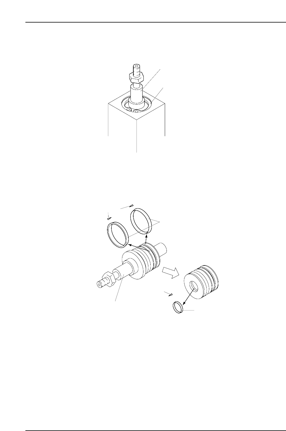
2. Use the snap ring pliers to remove the snap ring, and then pull the shaft from the
cylinder.
3. Clean the shaft and replace the 2 piston packings and the rod packing. Apply a
thin layer of grease (Alvania 2) to all moving surfaces.
Note: The packings are directional. The direction can be seen in the diagram cross-
sections.
4. Clean the inside of the cylinder, apply a thin layer of grease, (Alvania 2), and
reassemble the shaft in the cylinder.
Note: After replacing the packings, adjust the stopper according to the procedure in this
manual. (Part 5, Chapter 2-3 “Cam Lever Stopper Adjustment”)
CP6MR013
Packings
Packings
Packing
cross-sections
Packing cross-sections
Cylinder shaft
CP6MR012
Cylinder shaft
Snap ring
Part 3 Chapter 3 Replacing Consumable Parts
Edition 1.6 3-3-13 CP-6-series Mechanical Reference
3.8 Replacing the Vision Processing Halogen
Lamp
Procedure
Warning
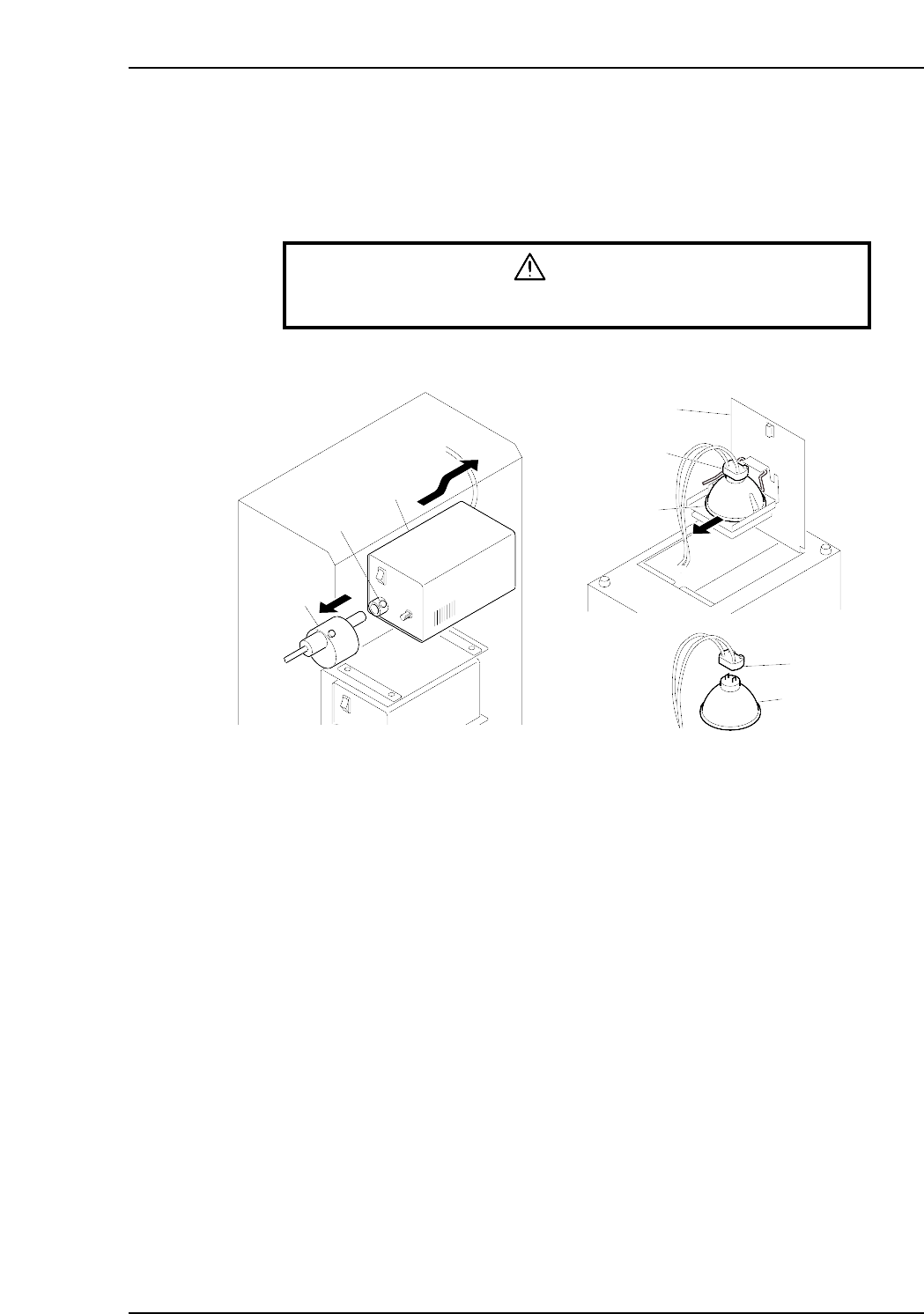
Turn off the 200 V servo power before carrying out this work.
1. Loosen the screw which secures the shutter to the light source unit, then detach
the shutter from the light source unit.
2. While supporting the light source unit, push it toward the rear of the machine to
extract it.
Note: If the light source cannot be extracted, use scissors, etc., to cut the tie-band which
secures the wires, being careful not to harm the wires.
3. After extracting the light source unit, turn it upside down and lift the latch to open
the cover.
4. Pull out the halogen lamp together with the socket.
5. Unplug the lamp from the socket, and plug in the new lamp.
Note: Avoid touching the lamp glass with your hands. Fingerprints, etc., on the lamp glass
can shorten its life.
6. Re-install the light source unit by reversing the above procedure.
Notes:
1. After returning the light source unit to its original position, be sure that the wiring is
not protruding toward the rear of the machine as it could catch on a feeder during
device table motion. To prevent this, push the wiring into the space between the
light source unit and the mounting face.
2. If the wiring tie-band was cut, attach a new tie-band.
CP6M3064E
Shutter
Screw
Light source unit
Socket
Socket
Cover
Halogen lamp
Halogen lamp
Part 3 Chapter 3 Replacing Consumable Parts
Edition 1.6 3-3-14 CP-6-series Mechanical Reference
3.9 Replacing the Mark Camera Lamp
Procedure
Warning
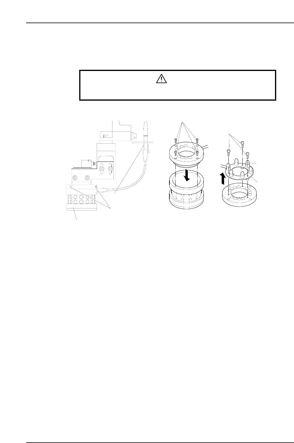
Turn off the 200 V servo power before carrying out this work.
1. Unplug the lamp unit's wiring connector.
2. Loosen the 3 screws which secure the lamp unit to the CCD camera to the point
where they protrude 1 to 2 mm from the lamp unit. Lower the lamp unit and
remove it.
Note: Use care to avoid dropping the lamp unit.
3. Remove the 4 screws which secure the top part of the lamp unit, then remove the
top part of the lamp unit.
4. After removing the top part of the lamp unit, turn it upside down and remove the
3 screws which secure the light bulb PCB, then remove the PCB together with its
wiring.
5. Unplug the failed light bulb and replace it with a new one.
Note: Avoid touching the lamp glass with your hands. Fingerprints, etc., on the lamp glass
can shorten its life.
6. Reassemble the lamp unit by reversing the above procedure, then mount the lamp
unit on the CCD camera, and plug in the wiring connector.
Note: With the 200V power on, press the [F] key and the [4] inching key simultaneously to
test the lamp operation (light bulbs switch on). Press these two keys again to turn
the lamp off.
CP6M3065E
Screws
Bolts
PCB
Light bulb
Wiring connector
Lamp unit mounting screws
Lamp unit