CP-6-series Mechanical Reference.pdf - 第154页
Notes: Part 4 Chapter 2 Leveling Edition 1.5 4-2-4 CP-6-series Mechanical Reference
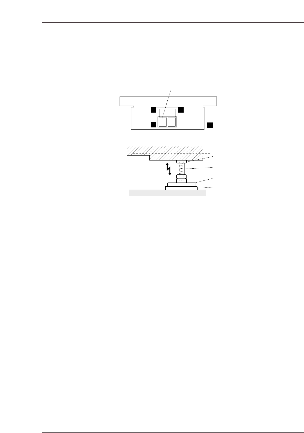
Procedure
To level the machine, place a sprit level on the unpainted surface of the main body of the
machine and adjust the leveling bolts while repeatedly checking the reading on the sprit
level.
Refer to the figure below for positioning of the spirit level and adjustment of the leveling
bolt.
XY-table
3 level check areas
Body
Lock nut
leveling bolt
leveling sheet
Vibration reduction pad
±15 mm
CP6M4017
Part 4 Chapter 2 Leveling
Edition 1.5 4-2-3 CP-6-series Mechanical Reference

Notes:
Part 4 Chapter 2 Leveling
Edition 1.5 4-2-4 CP-6-series Mechanical Reference
Part 4 Chapter 3 Air Supply
Edition 1.1 4-3-1 CP-6-series Mechanical Reference
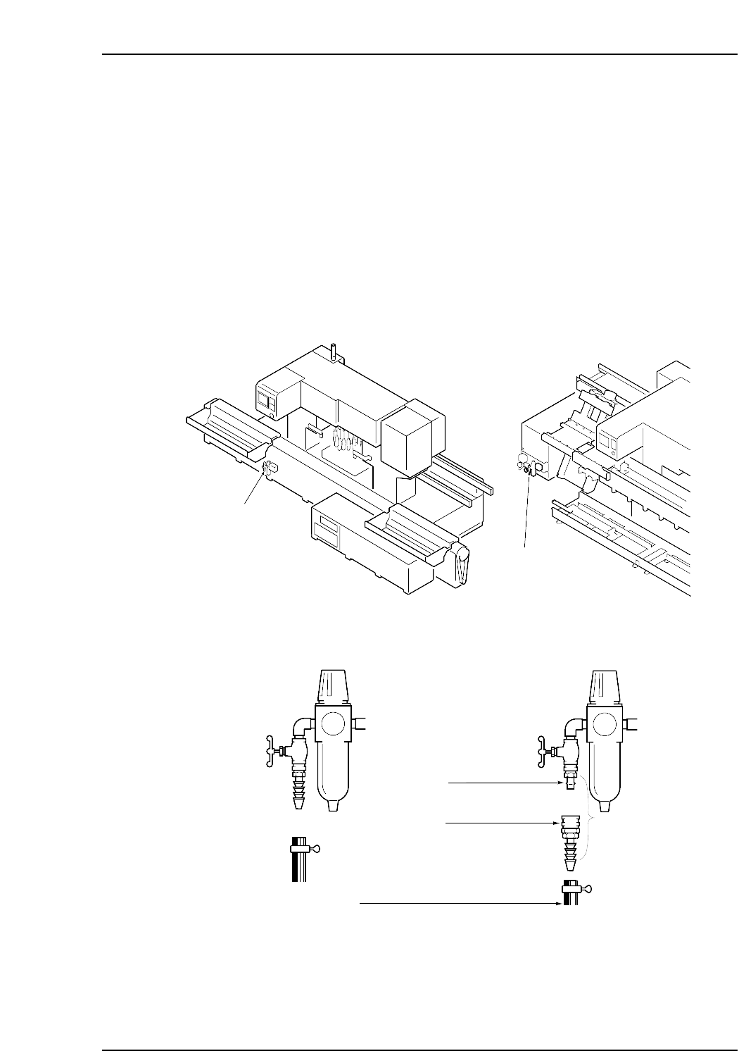
3. Air Supply
Point
Connect an external air supply hose to the machine and adjust the filter regulator to set
air pressure to the specified value.
Procedure
1. Attach a socket to the end of the air supply hose and connect the socket to the air
connector plug on the rear right-hand side of the machine.
2. Pull up the knob on the filter regulator to unlock it.
3. Turn the air inlet handle until the filter regulator reads 0.5 MPa (5 kgf/cm
2
).
4. Pull down the knob to lock it.
Note: Fuji does not supply the hose.
Plug (20 PM)
Hose (inner diameter: 8 mm)
Socket (20 SH)
Coupler
Standard
IEC compatible
CP6M4019
0.5 MPa (5 kgf/cm
2
)
Air inlet
Air inlet
(CP-652C only)
CP6M4018