CP-6-series Mechanical Reference.pdf - 第162页
Part 4 Chapter 5 Electric Power Supply Edition 1.3 4-5-4 CP-6-series Mechanical Reference Notes:
Edition 1.3 4-5-3 CP-6-series Mechanical Reference
Part 4 Chapter 5 Electric Power Supply
Checking the Three-Phase Cable Wiring
Follow the below steps to confirm that the three-phase wiring has been performed
correctly.
(1) Engage the 100 V power supply.
(2) Engage the 200 V power supply.
(3) Perform zero-setting.
(4) Press [AUTO]. Do not press the START button.
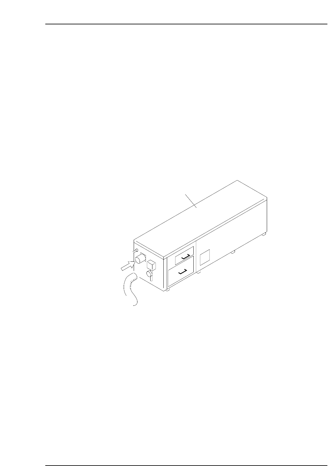
When [AUTO] is pressed, the vacuum pump in the noise reduction box at the rear of the
machine operates. Remove the hose to confirm that air is being sucked in. If air is being
sucked in, the wiring is correct and the motor is turning in the proper direction. If air is
being blown out, the user has crossed the U and V wires of the three-phase wiring.
Change these 2 wires and follow steps 1 to 4 again to confirm correct wiring.
Note: The CP-652C has a different shape of noise reduction box from the figure below. The
check procedure, however, is the same as stated above.
Noise reduction box
Air
CP6M4022

Part 4 Chapter 5 Electric Power Supply
Edition 1.3 4-5-4 CP-6-series Mechanical Reference
Notes:
Part 4 Chapter 6 Connecting the Communication Cable
Edition 1.0 4-6-1 CP-6-series Mechanical Reference
6. Connecting the Communication Cable
Point
Connect the CP-6 to the C/C (MCS) communication port using RS-232C cable to perform
data transmission and collect production information.
Procedure
1. Register the communication port number used for the CP-6 in the F4G (MCS) line
descriptor.
Note: Refer to the F4G (MCS) manual for detail information regarding the line descriptor.
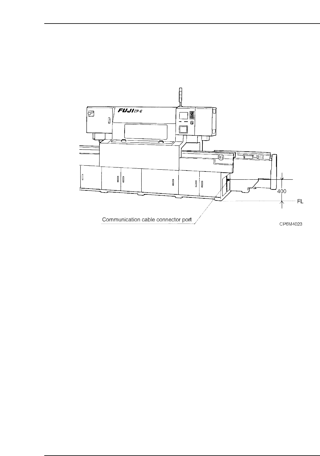
2. Connect one end of the RS-232C cable to the C/C (MCS) communication port
specified in the line descriptor and the other end to the port (DATA) on the right-
hand side of the machine.
Caution: It is necessary to use a shielded cable when using an RS-232C or other type of
interface cable.