CP-6-series Mechanical Reference.pdf - 第169页
Notes: Part 5 Chapter 1 Placing Head Edition 1.0 5-1-4 CP-6-series Mechanical Reference
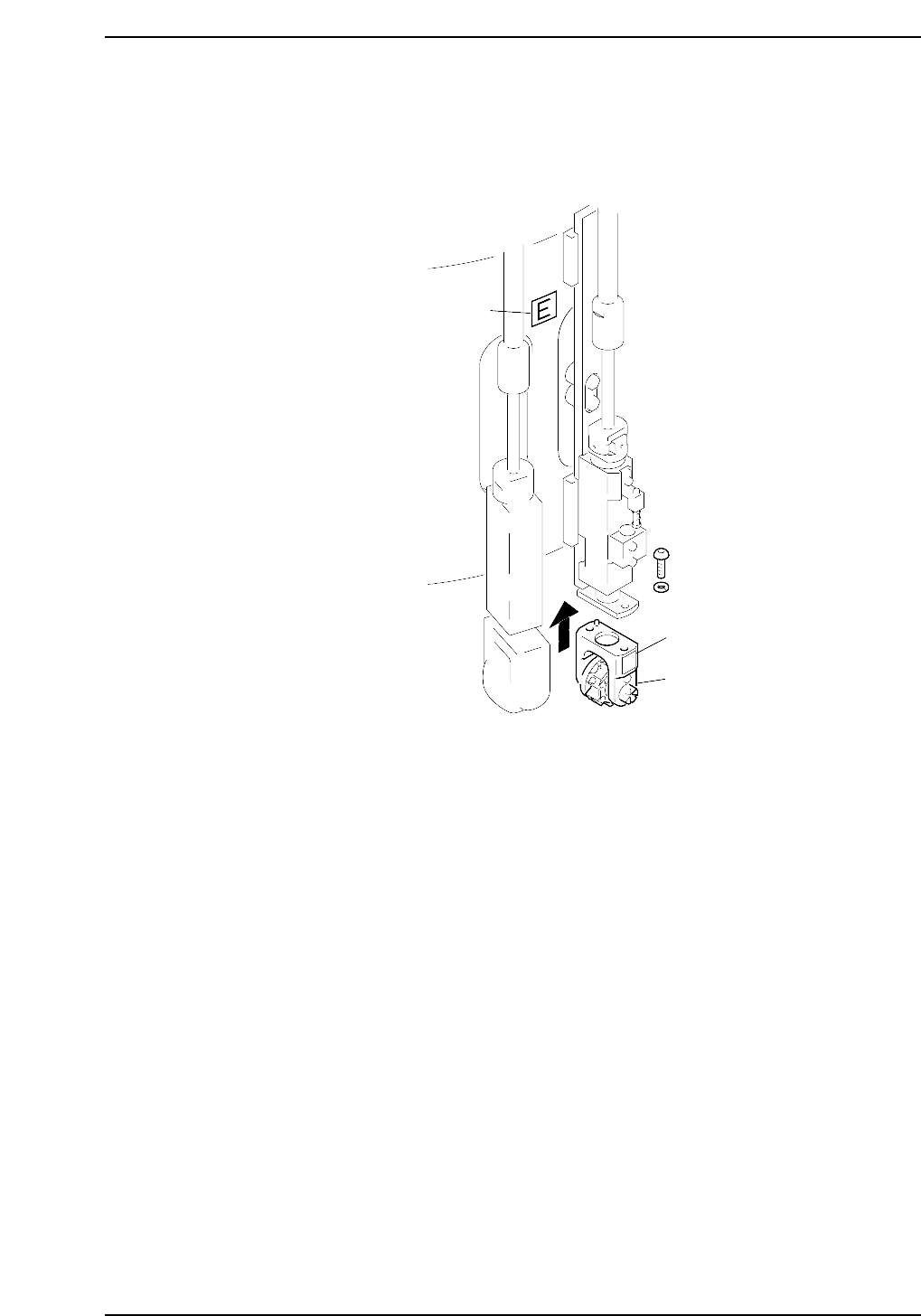
Installation
Install the nozzles such that the nozzle numbers match the seal numbers affixed to the
aluminum drums. The seal attached to the aluminum drum indicates the placing head
facing to the right so be sure not to install the wrong placing head.
Sticker
Sticker
E
Holder
CP6M5003
Part 5 Chapter 1 Placing Head
Edition 1.0 5-1-3 CP-6-series Mechanical Reference

Notes:
Part 5 Chapter 1 Placing Head
Edition 1.0 5-1-4 CP-6-series Mechanical Reference
Part 5 Chapter 2 Cam Box
Edition 1.6 5-2-1 CP-6-series Mechanical Reference
2. Cam Box
2.1 Timing Belt Tension Check (Cam Box)
WARNING
• Turn off the main power before carrying out this work.
• Exercise extreme caution when working on the machine if the cam is
not at its origin (0 deg.). Recoil of the cam axis can endanger the
operator.
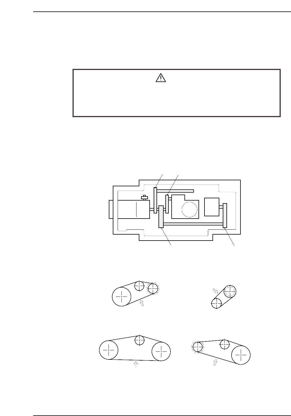
<4000 Type>
There are four timing belts in the cam box. With a finger flick the center of the timing
belt to start it oscillating. Measure the oscillation with a frequency meter and compare
the readout with the stipulated frequency values. Refer to figure below for belt location
and the figure for tension values.
• When measuring belt tension, make certain to set the tension pulley.
• Belts (c) and (d) are a set of two belts. Be sure to synchronize them.
• Even though belts (c) and (d) are a set, measure them one by one.
198 ±5Hz
83.5 ±5Hz
112 ±5Hz
72 ±5Hz
(a)
(d)
(c)
(b)
CP6M5007
Motor
(a)
(b)
(c)
(d)
CP6M5006