CP-6-series Mechanical Reference.pdf - 第174页
Part 5 Chapter 2 Cam Box Edition 1.6 5-2-5 CP-6-series Mechanical Reference 4. Turn the cylinder rod to adjust the clearance between the cam and the cam followers according to the following table. Caution: Improper gappi…
Part 5 Chapter 2 Cam Box
Edition 1.6 5-2-4 CP-6-series Mechanical Reference
2.3 Cam Lever Stopper Adjustment (Cam Box)
The cam lever stopper operates through the movement of the air cylinder. Usually the
air cylinder is in the retract position. At this position the cam operates. When the air
cylinder is in the extended position, the lever action is stopped.
The stoppers are used on the following seven functions.
Station 1 UP & DOWN NOZZLE
Station 1 FWRD & BWRD, FEEDING JAW
Station 3 UP & DOWN CLUTCH
Station 10 UP & DOWN, F•θ
Station 11 UP & DOWN, NOZZLE
Station 13 UP & DOWN, PR•θ
Station 18 FWRD & BWRD, KNOTCH
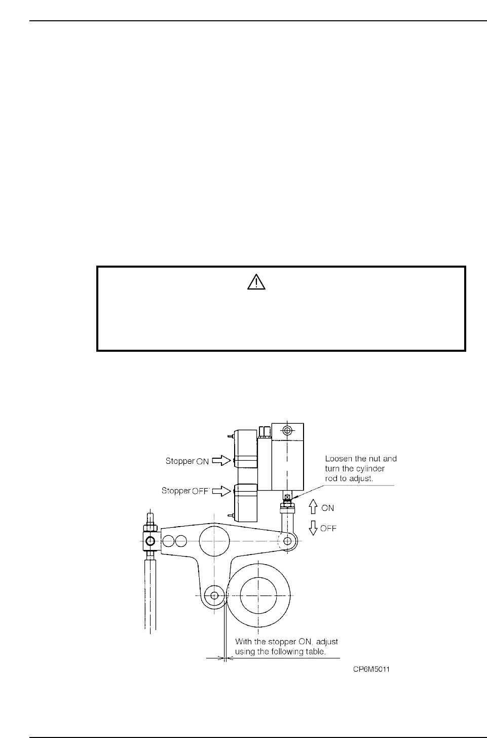
Adjustment procedure
WARNING
• Turn off the 200 V servo power before carrying out this work.
• Exercise extreme caution when working on the machine if the cam is
not at its origin (0 deg.). Recoil of the cam axis can endanger the
operator.
1. Set the cam to 0°.
2. Change the cylinder from the retract position to the extend position.
3. Attach a dial gauge to the end of the cam lever and set to zero.

Part 5 Chapter 2 Cam Box
Edition 1.6 5-2-5 CP-6-series Mechanical Reference
4. Turn the cylinder rod to adjust the clearance between the cam and the cam
followers according to the following table.
Caution: Improper gapping will damage the machine.
Station 1 nozzle up/down
Station 11 nozzle up/down
Station 1 feeder tape advance
Station 3 pre theta clutch up/down
Station 10 fine theta clutch up/down
Station 13 pre theta reverse up/down
Station 18 nozzle change
0.05 ~ 0.07 mm
0.05 ~ 0.07 mm
0.10 ~ 0.15 mm
0.10 ~ 0.15 mm
0.10 ~ 0.15 mm
0.10 ~ 0.15 mm
0.10 ~ 0.15 mm
Stopper Gap
CP6M5012
Part 5 Chapter 2 Cam Box
Edition 1.6 5-2-6 CP-6-series Mechanical Reference
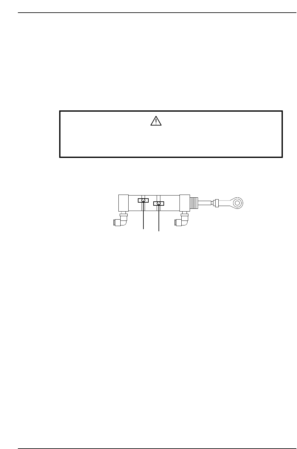
2.4 3rd/13th Station Air Cylinder Sensor Adjustment
The sensors on both cylinders for +90° and -90° should activate the moment either
rotation is complete.
Adjustment Procedure
1. Set the cam angle to 0°.
2. Activate the PQ +90° rotation by switching the I/O (Y024 PQ ROT. 90°) to ON.
3. Adjust the position of the sensor to activate when the cam angle is 210°~212°.
WARNING
Exercise extreme caution when working on the machine if the cam is
not at its origin (0 deg.). Recoil of the cam axis can endanger the
operator.
4. Similarly, to adjust the -90° sensor position, set the cam back to 0° and activate the
PQ -90° rotation by switching the I/O (Y025 PQ ROT. 270°).
5. Adjust the position of the sensor to activate when the cam angle is 210°~212°.
Pre-theta air cylinder
-90° rotation
+90° rotation
CP6M5013