CP-6-series Mechanical Reference.pdf - 第179页
Part 5 Chapter 3 Station Adjustments Edition 1.0 5-3-4 CP-6-series Mechanical Reference 3.1.2 T ape-end Detection It is possible to know when the tape is about to end due to a reflective sensor that detects the tape-end.…
Part 5 Chapter 3 Station Adjustments
Edition 1.0 5-3-3 CP-6-series Mechanical Reference
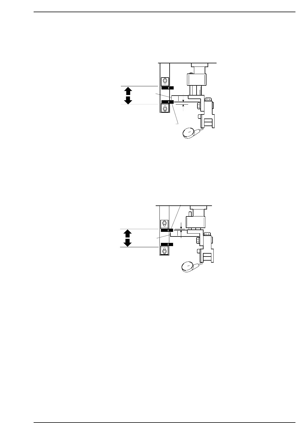
Advance Sensor Adjustment
1. When the dog is at the lower limit at cam angle 200°, ensure that the sensor is ON.
2. Set a dial gauge to the roller and adjust the sensor to go off 0.6 mm above the
lower limit.
Retract Sensor Adjustment
1. When the dog is at the upper limit at cam angle 0°, ensure that the sensor is ON.
2. Set a dial gauge to the roller and adjust the sensor to go off 0.3 mm below the
upper limit.
Dog upper limit
Dog lower limit
Dog
Retract sensor
0.3 mm
CP6M5017
0.6 mm
Dog upper limit
Dog
Dog lower limit
Advance sensor
CP6M5016
Part 5 Chapter 3 Station Adjustments
Edition 1.0 5-3-4 CP-6-series Mechanical Reference
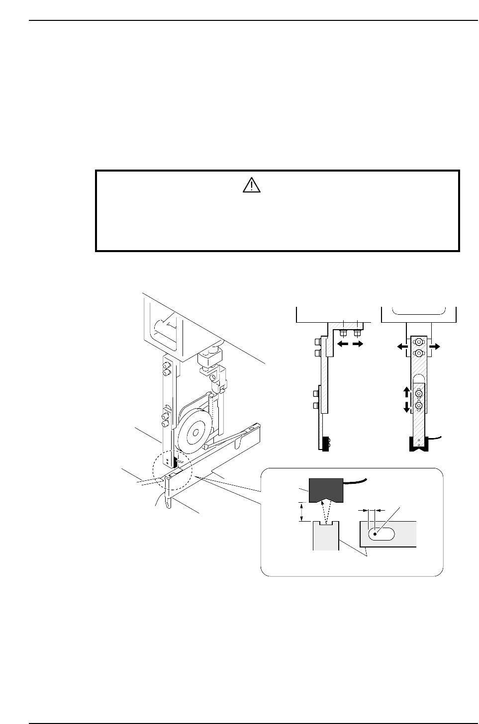
3.1.2 Tape-end Detection
It is possible to know when the tape is about to end due to a reflective sensor that detects
the tape-end.
Sensor Position Adjustment
1. Set an 8 x 4 mm tape feeder in the D1 position.
2. Press [SET] - [D pos] - [1] - [CR] and the START button to move the feeder to
station 1.
3. Press the EMERGENCY STOP button to take the 200 V down to 100 V.
WARNING
• Turn off the 200 V servo power before carrying out this work.
• Exercise extreme caution when working on the machine if the cam is
not at its origin (0 deg.). Recoil of the cam axis can endanger the
operator.
4. Ensure that the distance between the tape and the sensor is approximately 10 mm.
Sensor
11 ~12mm
2.5 mm
Feeder
Beam
Part 5 Chapter 3 Station Adjustments
Edition 1.0 5-3-5 CP-6-series Mechanical Reference
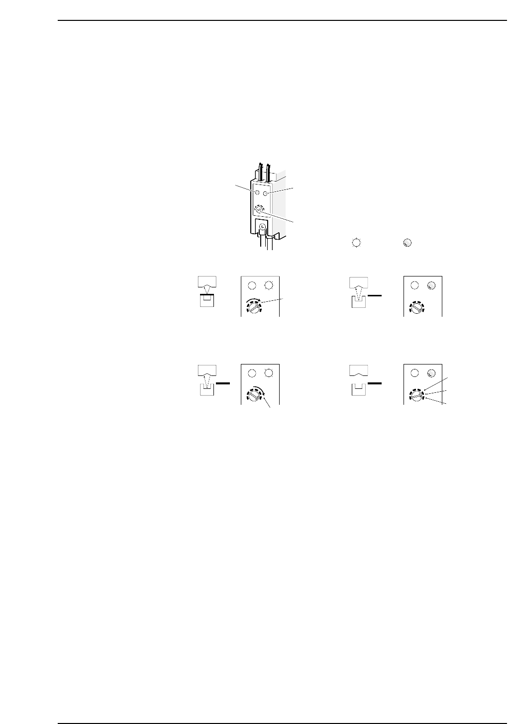
Sensor Sensitivity Adjustment
1. Rotate the sensitivity trimmer slowly to the right and ensure that the green LED
lights up at the A location.
2. Remove the paper tape from the feeder. The green LED should turn off at this
point.
3. Rotate the trimmer slowly to the right again and ensure that the green LED lights
up at the B location.
4. Set the sensitivity trimmer to be between A and B.
5. Ensure that the sensor actually detects the tape-end.
Red LED
Green LED
Trimmer
A
SET
(2)(1)
CP6M5019
B
(4)(3)
A
B
Lit Not lit