CP-6-series Mechanical Reference.pdf - 第183页
3.1.4 Nozzle V ertical Movement W ARNING Exercise extreme caution when working on the machine if the cam is not at its origin (0 deg.). Recoil of the cam axis can endanger the operator. Slider Adjustment 1. Adjust the he…
<5000 Type>
1. Press the EMERGENCY STOP button. This cuts the 200V servo power and leaves
on only the 100V power supply.
WARNING
• Turn off the 200 V servo power before carrying out this work.
• Exercise extreme caution when working on the machine if the cam is
not at its origin (0 deg.). Recoil of the cam axis can endanger the
operator.
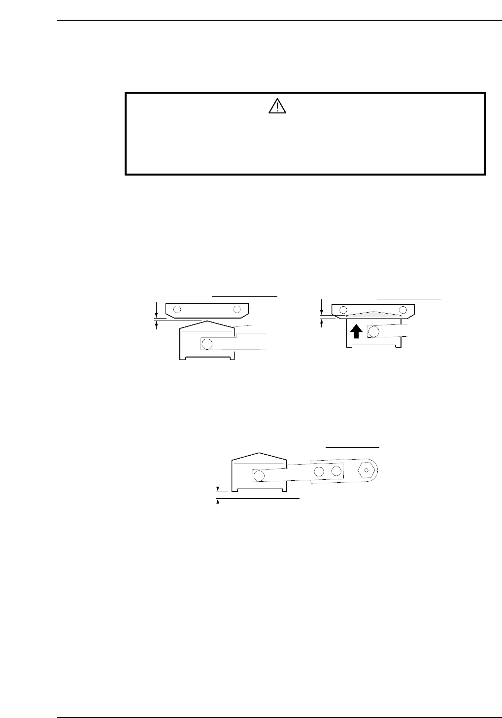
2. Rotate the cam using the handle to an angle of 153°.
3. Adjust the rod until the distance between the fixed blade and the moveable blade
is in the range of 0 ~ 0.3 mm.
4. Rotate the cam to an angle of 203°.
5. Ensure that the top edge of the moveable cutter overlaps the fixed cutter by more
than 1.0 mm.
6. Rotate the cam to 0°.
7. Ensure that there is a gap of more than 1.5 mm between the lower edge of the
moveable blade and the surface below.
More than 1.5 mm
CP6M5023
Cam angle 0°
Fixed blade
Movable blade
0 ~ 0.3 mm
More than
1.0 mm
Cam angle 153°
Cam angle 203°
CP6M5022
Part 5 Chapter 3 Station Adjustments
Edition 1.0 5-3-7 CP-6-series Mechanical Reference
3.1.4 Nozzle Vertical Movement
WARNING
Exercise extreme caution when working on the machine if the cam is
not at its origin (0 deg.). Recoil of the cam axis can endanger the
operator.
Slider Adjustment
1. Adjust the height of the slider to ensure that the cam follower can travel smoothly
through the slider and along the cam groove.
Select [SET] - [MANUAL] - [I/O] and then press the EMERGENCY STOP button
to take the 200 V down to 100 V.
WARNING
Turn off the 200 V servo power before carrying out this work.
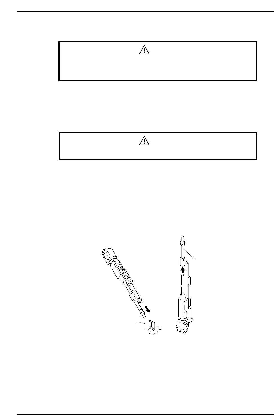
2. Rotate the cam to 0°, then use a spanner to remove the clutch from the nozzle shaft
near station 11. Once the bolt is loosened rotate it with your fingers to remove it.
(See the illustration on the next page.)
3. Remove the nozzle axis brackets and the vacuum hose, then remove the nozzle
shaft assembly. (See the illustration on the next page.)
Caution: When removing the nozzle shaft assembly, take care not to dislodge the bearings.
There are no stoppers to prevent the bearings from sliding off. Do not remove the
outer shaft.
Bearing
Outer shaft
CP6M5024
NG
NG
Part 5 Chapter 3 Station Adjustments
Edition 1.0 5-3-8 CP-6-series Mechanical Reference
Caution: Do not disassemble the nozzle shaft assembly carelessly. Special equipment and skills
are required to perform the reassembly of the nozzle shaft. Such procedures should be
attempted only by users who have attended training at Fuji and are equipped with
the necessary tools, or whilst under the direct guidance of a serviceman.
Bracket
Linear guide
Outer shaft
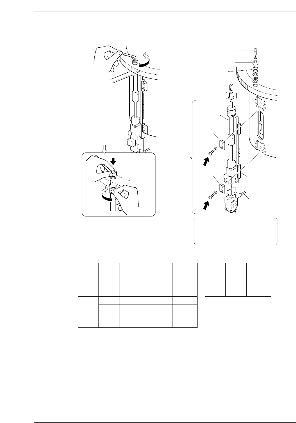
Clutch
Bolt
Caution : Washers may jump when the bolt
is loosened because of the spring
under the clutch.
Spring
Use a torque wrench to apply
20 kgf.cm to the screws (A and B)
when attaching the nozzle axis.
Refer to the table below.
Rotate the nozzle shaft
while holding the bolt
with your finger
A
B
X No. Part
Bolt
size
Bracket
No.
Torque
Kgf/cm
~ 166
167 ~
260
261
A
B
A
B
A
B
M4
M4
M4
M5
M4
M5
WPH0331
WPH0331
WPH0331
WPH1031
WPH0331
WPH1020
20
33
20
40
20
40
A
B
M4
M4
20
20
(4000 TYPE) (5000 TYPE)
Bracket
Vacuum hose
Part
Bolt
size
Torque
Kgf/cm
CP6M5025
Nozzle
shaft
assembly
Part 5 Chapter 3 Station Adjustments
Edition 1.0 5-3-9 CP-6-series Mechanical Reference