CP-6-series Mechanical Reference.pdf - 第193页
3.1.7 Raised Feeder Detection At station 1 there are sensors below and above the feeder to detect any feeder lift. Adjust the sensitivity and the installation positions of these sensors. Top Feeder Lift Sensor Adjustment…
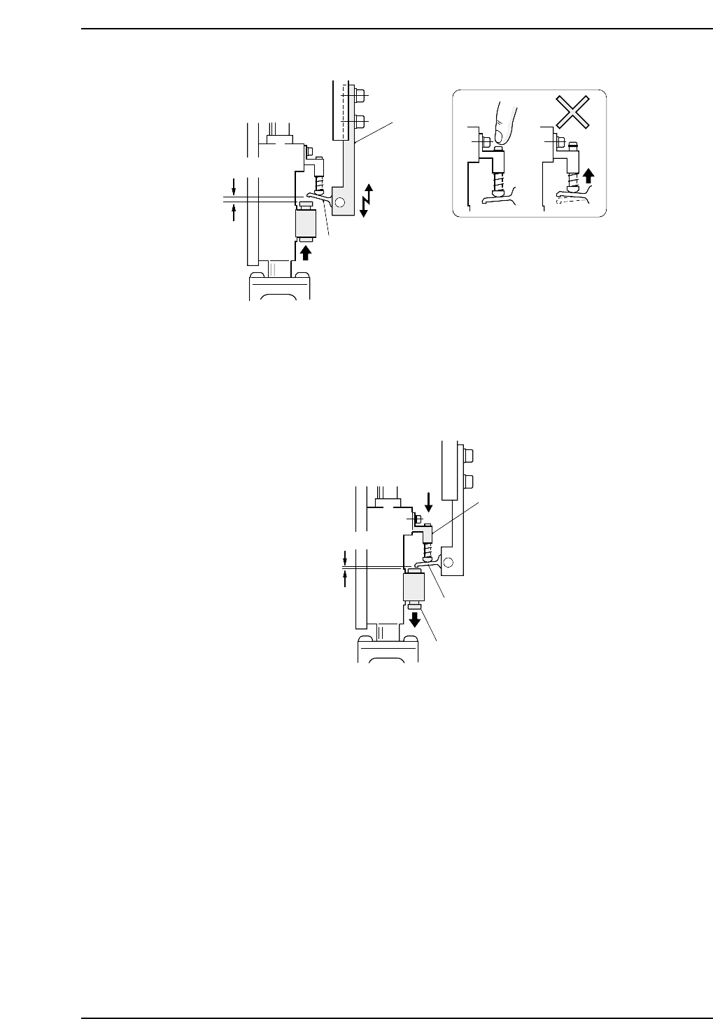
4. Set the cam angle to 0°, then turn on the solenoid (Y020 PICK UP SOL ON) to
work the lever.
5. Use the cam handle to rotate the cam to 175°.
6. Ensure that the distance between the spool pushed down by the lever, and the
lever itself is 0 ~ 0.1 mm at all heads.
0 ~ 0.1 mm
Bracket
Lever
Spool
CP6M5035
0.7 mm
Lever
Caution : Press down on
the pin to prevent
it from raising.
Bracket A
CP6M5034
Part 5 Chapter 3 Station Adjustments
Edition 1.0 5-3-17 CP-6-series Mechanical Reference
3.1.7 Raised Feeder Detection
At station 1 there are sensors below and above the feeder to detect any feeder lift. Adjust
the sensitivity and the installation positions of these sensors.
Top Feeder Lift Sensor Adjustment
WARNING
Turn off the 200 V servo power before carrying out this work.
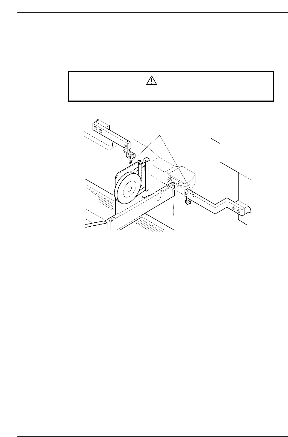
1. Ensure that the feeders are set correctly on the device table (refer to Part 2, Chapter
2 “Feeder Setting”).
2. Move the device table right and left to ensure that the feeder does not collide with
the sensor bracket or break the light beam.
Feeder lift sensor
Light beam
CP6M5036
Part 5 Chapter 3 Station Adjustments
Edition 1.0 5-3-18 CP-6-series Mechanical Reference
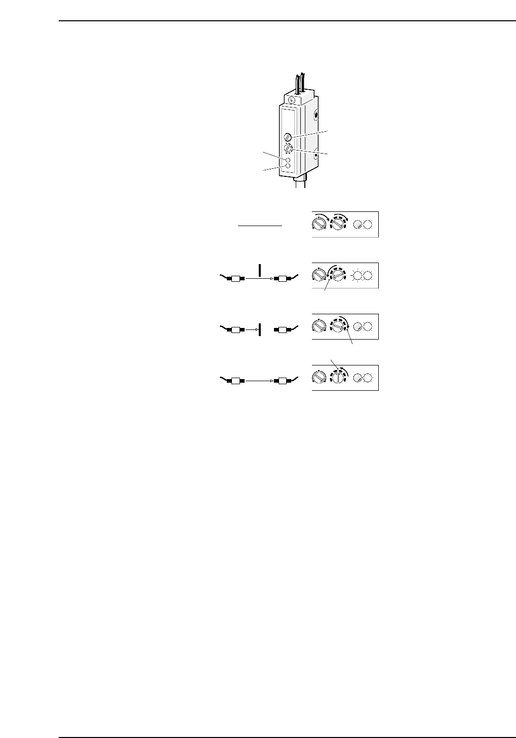
Sensor Sensitivity Adjustment
1. Rotate volumes 1 and 2 all the way to the right.
2. Pass the beam to the receiver. Slowly rotate volume 2 to the left until the red LED
(position A) lights up.
3. Break the light beam with a ruler (or something similar) and slowly rotate volume
2 to the right from (A) until the red LED goes out (position B).
4. Set volume 2 in between (A) and (B).
MAXMIN
+
-
MAXMIN
+
-
MAXMIN
+
-
MAXMIN
+
-
Red LED
Green LED
Volume 1
Volume 2
SET
(1)
(2)
(3)
(4)
(B)
(A)
CP6M5037
Part 5 Chapter 3 Station Adjustments
Edition 1.0 5-3-19 CP-6-series Mechanical Reference