CP-6-series Mechanical Reference.pdf - 第225页
Notes: Part 5 Chapter 4 Engagement Rail Adjustments Edition 1.0 5-4-4 CP-6-series Mechanical Reference
<X No. 423 model used hereafter>
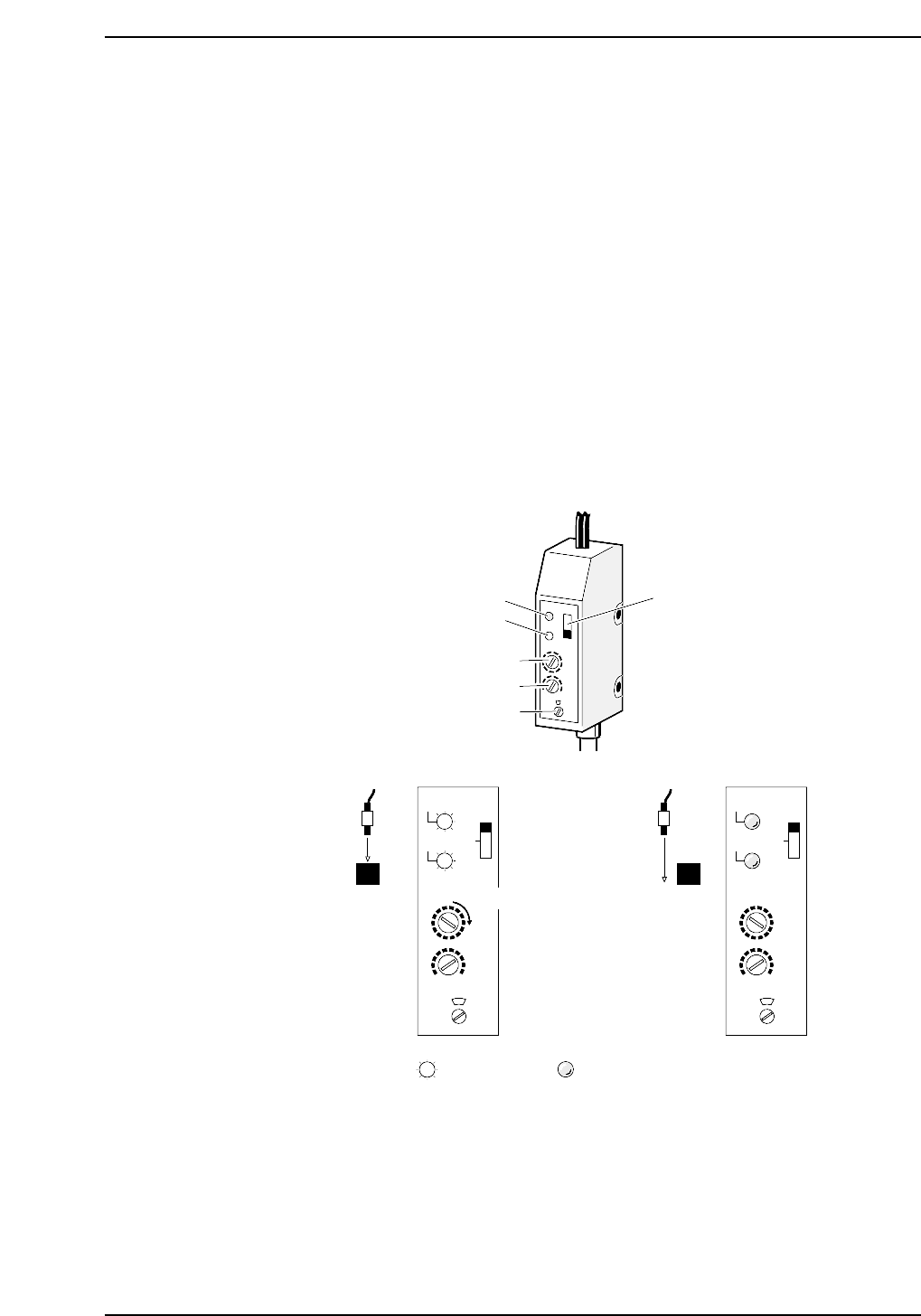
1. Set the sensor amp ALM switch to OFF, TIME to 0.04 seconds, and MODE to 1.
2. Move the XY-table to the loading position and adjust the sensitivity using volume
1 so that both the red and green LED light up (ON) at the Z0 position and both
LEDs go out (OFF) moving away from this position.
(1) Move the XY-table to the loading position and set the Z0 position.
(2) Rotate the volume 1 dial so that both the red and green LED light up when
the sensor is at the engage position (silver portion). Turn the dial about two
positions in the clockwise direction from the position where the light comes
on.
3. Check the sensor operation at the next point.
• When the sensor is at the engage position (silver portion), confirm that both
the red and green LED light up when the XY-table height is between the Z0
position and the position where the upper limit sensor comes on.
• When the sensor is not at the engage position (when it is at the black
portion), verify that both the red and green LED go off with the table height
between the Z0 position and the position at which the upper limit sensor
comes on.
Red LED
ALM switch
Green LED
Volume 1
Volume 2
Volume 3
(SEC.)TIME
MODE
SENS.
5
1
0.04
OFF
OUT
STB
STB
(1) (2)
CP6M5073
OUT
ALM
(SEC.)TIME
MODE
SENS.
5
1
0.04
OFF
OUT
STB
STB
OUT
ALM
Lit Not lit
Greater sensitivity
Part 5 Chapter 4 Engagement Rail Adjustments
Edition 1.0 5-4-3 CP-6-series Mechanical Reference

Notes:
Part 5 Chapter 4 Engagement Rail Adjustments
Edition 1.0 5-4-4 CP-6-series Mechanical Reference

Part 6
I/O