CP-6-series Mechanical Reference.pdf - 第231页
1.4 Reading the I/O Map List A description of the I/O map fields is given below: LED # PORT# STATE DISPLAY PAGE DESCRIPTION LED # Refers to the LED # on the various I/O modules of the PLC's. It is also the Terminal …

1.3 Using the I/O Map
Using the I/O map is quite simple. Once in the I/O menu, the operator has a choice to
choose the Input side to work with, or the Output side. Only one side may be accessed
at a time (although both are displayed on the screen at the same time). When a side is
selected, the [PAGE +] and [PAGE -] keys become active. Locate the desired port with
these keys. The UP and DOWN arrow keys may also be used to move the cursor one
port location at a time.
The Input side only reports the current input state of the port. If the the input terminal is
connected to DC ground, then a green ‘0’ (active) will appear in the I/O MAP for that
port address. Otherwise, a yellow ‘X’ (not active) will appear for that port. If the cursor
is on the port and the port is active, then the buzzer will be turned ON.
The Output side allows the operator to change the state of the port with the ON/OFF
key. Pressing this key will toggle the current state of the output port. A yellow ‘X’
means ‘not active’ and a green ‘0’ means ‘active.’
I/O Map Example
I/O MAP
X021 X
Air OK
LX009 0 Main PCB Conf
Y021 X Nozzle Blow 1
LX008 0 Out-Conveyor ON
INPUT OUTPUT
CP6M6002
Part 6 Chapter 1 The Machine I/O
Edition 1.0 6-1-4 CP-6-series Mechanical Reference
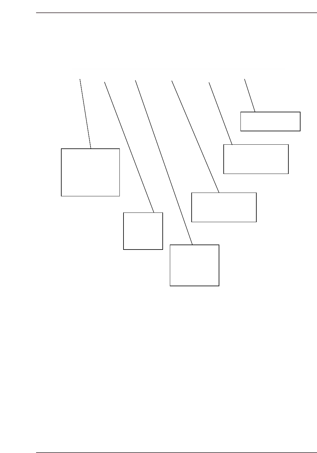
1.4 Reading the I/O Map List
A description of the I/O map fields is given below:
LED # PORT# STATE DISPLAY PAGE DESCRIPTION
LED #
Refers to the LED #
on the various I/O
modules of the PLC's.
It is also the Terminal
number that the wire
carrying the input
signal is connected to.
A00 X000 EMERGENCY SW Emergency Stop button016
Port #
The I/O Port ad-
dress. It is also
the wire number
of the wire carry-
ing the input signal.
State
The state of the I/O
signal after power-
ing on the machine,
Zero-setting the machine
and pressing AUTO
and no alarms indicated.
Display
Refers to what is displayed by
the machine as the formal
name of the port.
Page
Refers to what page
the port can be located at in the
electrical schematic.
Description
A more detailed description
of the port
Figure: I/O Map List Description
CP6M6003
Part 6 Chapter 1 The Machine I/O
Edition 1.0 6-1-5 CP-6-series Mechanical Reference
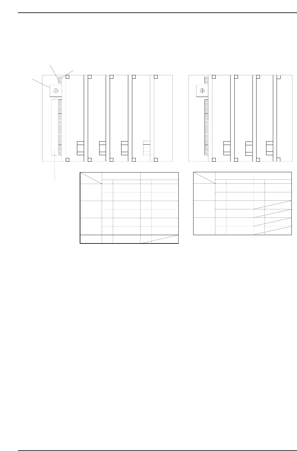
1.5 MX 250 I/O Configuration
This is the arrangement of the LEDs that display in control box 1 for MX 250 I/O boards.
0
1
2
3
4
5
6
7
8
9
A
B
C
D
E
F
2A. Fuse
2A. Fuse
2A. Fuse
I/O-1 I/O-2 I/O-3 I/O-4
INPUT OUTPUT
SW.# SW.#
Address Address
I/O-1
I/O-2
I/O-3
0
1
2
3
4
5
6
8
9
A
B
C
D
A00 ~ A0F
B00 ~ B0F
A00 ~ A0F
B00 ~ B0F
A00 ~ A0F
B00 ~ B0F
A00 ~ A0F
A00 ~ A0F
B00 ~ B0F
A00 ~ A0F
B00 ~ B0F
A00 ~ A0F
B00 ~ B0F
0
1
2
3
4
5
6
7
8
9
A
B
C
D
E
F
2A. Fuse
LI/O-1 LI/O-2
INPUT OUTPUT
SW.# SW.#
Address Address
LI/O-1
LI/O-2
0
1
2
3
4
5
8
9
A00 ~ A0F
B00 ~ B0F
A00 ~ A0F
B00 ~ B0F
A00 ~ A0F
B00 ~ B0F
A00 ~ A0F
B00 ~ B0F
Power ON
Transmission Error
Rotary Selector
Switch
I/O Function
Indicators
2A. Fuse
2A. Fuse
LI/O-3
LI/O-3
2A. Fuse
I/O-4
To monitor the I/O, simply select the proper inport or outport. Each I/O port controls 32 inputs and
outputs address number (listed in the System Reference Manual) and set the rotary selector switch as
indicated in the chart above.
Direct I/O
Loader I/O
CP6M6004
Part 6 Chapter 1 The Machine I/O
Edition 1.0 6-1-6 CP-6-series Mechanical Reference