CP-6-series Mechanical Reference.pdf - 第243页
5. Initializing ST11 Proper Data The Proper data must be changed to “0” by a manual input using the PAM editor commands. The ST11 Proper data will have been transmitted from the host computer (MCS or F4G) to the machine …

2.6 ST11 Proper Data Setting Procedure
Follow the procedures listed below to adjust the Proper data for station 11.
Procedure
1. Replace the Nozzles
Install 1.3 mm nozzles (with 12 mm reflective disks) in all the nozzle holders.
2. Mounting the Cartridge
PAM requires only 1 cartridge for a paper tape (width: 8 mm, feed pitch: 4 mm). The
PAM dummy parts reel is set on the cartridge, and the cartridge is then mounted on
device number 1.
3. Loading the PAM Measurement Board
Use the [LOADER] command to load the PAM measurement board.
Note: In the PAM mode, the [LOADER] command must always be used to load and unload the
board.
4. Nozzle Center Measurement
Perform a nozzle center measurement. The Nozzle Assignment Table should be such
that nozzles with bend amounts of 0.05 mm or more are skipped.
Replace the unacceptable nozzles, then repeat the nozzle center measurement using the
following command sequence:
[SET] → [MANUAL] → [NOZZLE] → [CENTER] → START button
Note: Refer to 2.1 “The Need for Station 11 Proper Data Calibrations” section of this chapter for
information concerning the necessity of nozzle center measurements.
Part 7 Chapter 2 Placement Accuracy Measurement
Edition 1.0 7-2-7 CP-6-series Mechanical Reference
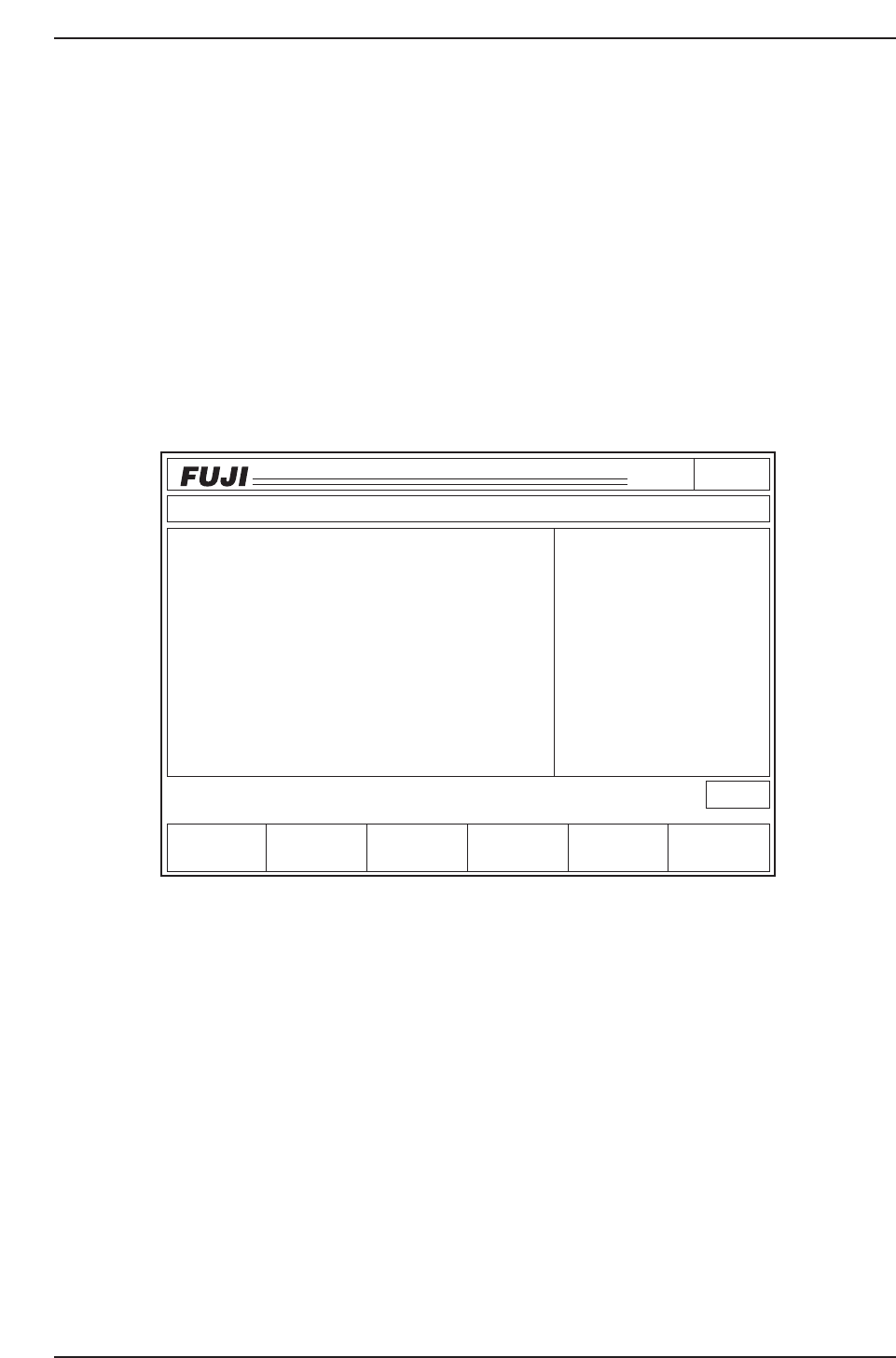
5. Initializing ST11 Proper Data
The Proper data must be changed to “0” by a manual input using the PAM editor
commands.
The ST11 Proper data will have been transmitted from the host computer (MCS or F4G)
to the machine (current machines).
Using the PAM editor commands, initialize this ST11 Proper data (Proper X, Proper Y)
by entering “0” for each of the 1 to 6 nozzles at each head.
1. Execute the following command sequence:
PAM [EDITOR] —> [NOZZLE TYPE] —> [SELECT NZL]
(select the number of the nozzle being measured)
2. Use [F] + [F4] to copy the dx and dy “0” values to Proper X ,Y.
Note: When the dx and dy values are other than “0” (factory correction values are entered),
change all the Proper X, Y values to “0” by manual input.
Page150
CP_6.PROGRAM
000000000000
000000000000
Prod 00004 Sche 00000
P1.00 off line
Operation: Front
Ready
Return
jog
XY
C
∆
Proper Input Data Data Save
Proper data
∇
HEAD
A
B
C
D
E
F
G
H
I
J
Proper X
- 7
- 4
- 7
- 5
- 7
- 5
- 6
- 4
- 8
- 3
Avg.dX
- 2
- 1
- 2
- 1
- 2
- 2
- 2
- 1
- 3
- 1
2
1
0
1
1
0
1
1
1
0
Proper Y
3
2
2
3
1
2
3
3
1
0
Avg.dY
Nozzle type 2
X Y dX dY [1/100mm]
Nozzle Skip
1 AB CD EF 2 AB CD EF
3 AB CD EF 4 AB CD EF
5 AB CD EF 6 AB CD EF
CP6M7007
Part 7 Chapter 2 Placement Accuracy Measurement
Edition 1.0 7-2-8 CP-6-series Mechanical Reference

6. Placing Dummy Parts
After initializing all heads, end the editor command mode, then use the placing
commands to place the parts.
1. Press [RETURN] to return to the initial screen.
2. Select [PAM] —> [PLACE].
3. Press the START button.
4. Press the START button again to begin part placement.
7. Dummy Parts Measurement
After the dummy parts have been placed, use the measurement command to measure
them with the board still on the XY-table. This procedure consists of measuring the
amount of deviation from the program coordinate values (nozzle center measurement
values).
1. Select [MEASUREMENT]
The XY-table begins to move, and the fiducial mark camera acquires images of the
actual positions where the parts have been placed. This is followed by statistical
processing.
2. Deviation display
i) Select the following commands:
[EDITOR] —> [NOZZLE TYPE] —> [SELECT NZL]
(select the number of the nozzle being measured)
ii) Check the Avg. dx, and dy values.
Note: A correction is required if the deviation exceeds 10 (0.1).
3. Proper data correction
The following is the correction procedure which must be performed at placing
heads where the deviation (Avg. dx, dy) exceeds 10.
i) When the Avg. dx, and dy values exceed 10, add half their value to the
Proper X, Y values.
Example:
Proper X
6
Proper X
12
Proper Y
-7
Proper Y
-15
Avg.dx
12
Avg.dy
-16
CP6M7008
Part 7 Chapter 2 Placement Accuracy Measurement
Edition 1.0 7-2-9 CP-6-series Mechanical Reference