CP-6-series Mechanical Reference.pdf - 第246页
10. Transmitting Proper Data From Machine to Host Transmit (and back-up) the Proper data from the machine to the host (F4G or MCS). This completes the ST11 Proper data adjustments using PAM. Tolerance range After the PAM…

Notes: The deviation in the placement position is corrected by correcting the Proper data.
Attempts to perform a 100% correction will result in an over-correction, and will cause
an even greater deviation (overshoot). Therefore, only 1/2 of the calculated value
should be added (never add the full value).
ii) If the deviation (Avg. dx, dy) is 10 or less,, repeat Step 6 “Placing Dummy
Parts” to the end of Step 7 “Dummy Parts Measurement” procedure shown
above.
8. Results Display
9. Sig. X, Y, Q (3-Sigma) Check
1. Select the [RESULTS] command.
2. The correction procedure is complete if all the sig. X, Y, Q values are 100 or less. If
any values exceed 100, repeat Step 6 “Placing Dummy Parts”, then check the sig.
X, Y, Q values again.
3. Select the [DATA SAVE] command.
Continue with the Proper data corrections for all the other nozzles.
Page141
CP_6.PROGRAM
000000000000
000000000000
Prod 00000 Sche 00000
P1.00 off line
Operation : Front
Ready
RETURN
jog
XY
C
SIZE
PRINT
Avg.dX
- 13
Max.dX
26
Max.dX
- 13
3sig.X
- 18
Avg.dQ
- 278
Max.dQ
476
Max.dQ
- 278
3sig.Q
483
- 9
Avg.dY
19
Max.dY
- 9
Max.dY
4
3sig.Y
Data Display
Measurement Result
Nozzle Type
All Nozzle
All degrees
All data
5000
dXdY
[1/1000mm]
dQ
[1/1000deg]
CP6M7009
Part 7 Chapter 2 Placement Accuracy Measurement
Edition 1.0 7-2-10 CP-6-series Mechanical Reference

10. Transmitting Proper Data From Machine to Host
Transmit (and back-up) the Proper data from the machine to the host (F4G or MCS).
This completes the ST11 Proper data adjustments using PAM.
Tolerance range
After the PAM measurement is completed, the following information can be output (to
the printer if connected) for all number 1 to 6 nozzles: deviation amount, deviation
average, max./min. deviation, accuracy result.
Fuji guarantees a CP-6 placing accuracy of ±0.1 mm. However, because machine
efficiency can vary due to maintenance and operating conditions, it is impossible to
group all machines into one tolerance range. Keep this in mind when deciding the best
placing accuracy for your specific machine in order to obtain better results from the
calibration process.
2.7 Placing Accuracy Verification
1. Use a mark reference board to adjust the ST11 Proper data.
2. With the Proper data set (step 1 above), perform the part placement and
measurement operations using a pin reference program. Verify that the accuracy
is acceptable.
Part 7 Chapter 2 Placement Accuracy Measurement
Edition 1.0 7-2-11 CP-6-series Mechanical Reference
2.8 Downloading Measurement Results to a PC
This procedure consists of downloading data lines, and it requires the following
environment.
• A Windows computer with NTCC installed.
• The Digi board (RS232C expansion port recommended by Fuji).
• Machine <—> PC transmission cable (Dwg. No. EEHH1061 or EEHH1071).
2.8.1 Procedure at Machine
1. Using the machine commands, proceed to “Page: Data Save-3”, then select the
[Change Port] command to specify the port (CH1 or CH2) where the data is to be
output.
2. Connect the transmission cable to the specified port.
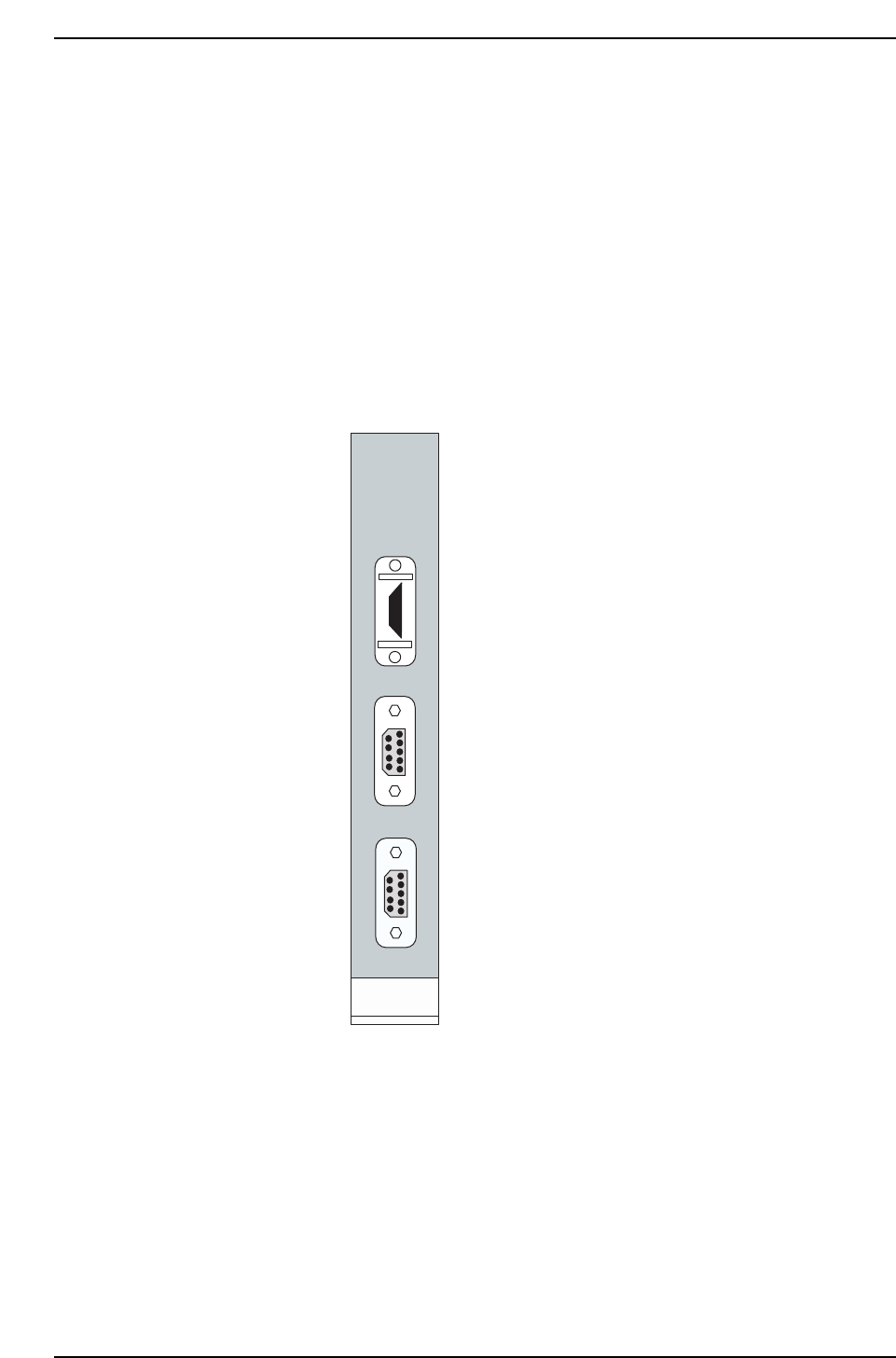
The machine’s CPU board is
equipped with a printer port and 2
RS232C ports as shown at left.
The “RS232C 1” port is CH1.
The “RS232C 2” port is CH2.
When transmitting Proper data
using an RS232C port, the data line is
connected from the machine’s side-
face connector to CH1 by internal
wiring. In this case, production
information (PT) is also sent to the
host from CH1. The connector
should therefore be connected to
CH2.
Use the [Change Port] command to
specify CH2.
When using the internal CC, either
CH1 or CH2 may be used. In this
case, the machine <—> PC
transmission cable must be
connected to the machine’s side-face
connector. (Transmission cable
Dwg. No.: EEHH1061 or EEHH1071)
PRINTER
RS232C 1
RS232C 2
HIMV-134
CP6M7010
Part 7 Chapter 2 Placement Accuracy Measurement
Edition 1.0 7-2-12 CP-6-series Mechanical Reference