CP-6-series Mechanical Reference.pdf - 第248页
2.8.2 Procedure at PC Setting the Communication Conditions 1. At the PC side, connect the transmission cable (machine <—> NTCC) to the port which is not being used by NTCC. If there are no vacant ports, leave the c…
2.8 Downloading Measurement Results to a PC
This procedure consists of downloading data lines, and it requires the following
environment.
• A Windows computer with NTCC installed.
• The Digi board (RS232C expansion port recommended by Fuji).
• Machine <—> PC transmission cable (Dwg. No. EEHH1061 or EEHH1071).
2.8.1 Procedure at Machine
1. Using the machine commands, proceed to “Page: Data Save-3”, then select the
[Change Port] command to specify the port (CH1 or CH2) where the data is to be
output.
2. Connect the transmission cable to the specified port.
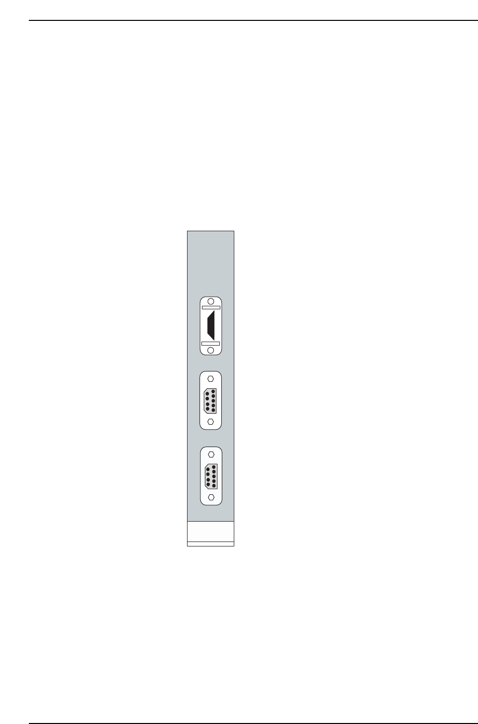
The machine’s CPU board is
equipped with a printer port and 2
RS232C ports as shown at left.
The “RS232C 1” port is CH1.
The “RS232C 2” port is CH2.
When transmitting Proper data
using an RS232C port, the data line is
connected from the machine’s side-
face connector to CH1 by internal
wiring. In this case, production
information (PT) is also sent to the
host from CH1. The connector
should therefore be connected to
CH2.
Use the [Change Port] command to
specify CH2.
When using the internal CC, either
CH1 or CH2 may be used. In this
case, the machine <—> PC
transmission cable must be
connected to the machine’s side-face
connector. (Transmission cable
Dwg. No.: EEHH1061 or EEHH1071)
PRINTER
RS232C 1
RS232C 2
HIMV-134
CP6M7010
Part 7 Chapter 2 Placement Accuracy Measurement
Edition 1.0 7-2-12 CP-6-series Mechanical Reference

2.8.2 Procedure at PC
Setting the Communication Conditions
1. At the PC side, connect the transmission cable (machine <—> NTCC) to the port
which is not being used by NTCC. If there are no vacant ports, leave the cable as it
is, and end NTCC. (When NTCC is ended, acquisition of production information
from other machines is disabled.)
2. When using Windows NT 3.51
i) Start up the communication software at the PC as follows: “Program
Manager” —> “Accessories” —> “Terminal”.
ii) At the Terminal menu, select “Settings” —> “Communication Conditions”,
then specify the following settings:
Communication speed (bps): 9600
Flow control: Xon/off
Serial port: COM?
(PC port connected to transmission cable)
Data length: 8
Stop bit: 1
Parity: None
iii) At the menu, select [File] —> [Save As] to save the setting conditions. Once
saved, these settings are convenient when using the trace port (e.g.
trace.trm).
3. When using Windows NT 4.0
i) Click the START button, select “Accessories”, then start up the Hyper
Terminal.
ii) Enter the name (e.g., trace) at the connection settings, select the icon, then
click OK.
iii) Select the PC port (COM?) where the transmission cable is connected, then
click OK.
iv) At the port settings, specify the same settings as those at 2-ii) above, then
click OK.
v) At the menu, select [File] —> [Save] to save the setting conditions. A
shortcut is created at the START button (e.g. trace.ht).
Part 7 Chapter 2 Placement Accuracy Measurement
Edition 1.0 7-2-13 CP-6-series Mechanical Reference

Notes:
Part 7 Chapter 2 Placement Accuracy Measurement
Edition 1.0 7-2-14 CP-6-series Mechanical Reference