CP-6-series Mechanical Reference.pdf - 第256页
Notes: Part 8 Chapter 2 D-Axis Carrier Edition 1.0 8-2-4 CP-6-series Mechanical Reference
2.2 Adjustment of the Pallet-position Confirmation
Sensors
Warning
Turn off the 200 V servo power before carrying out this work.
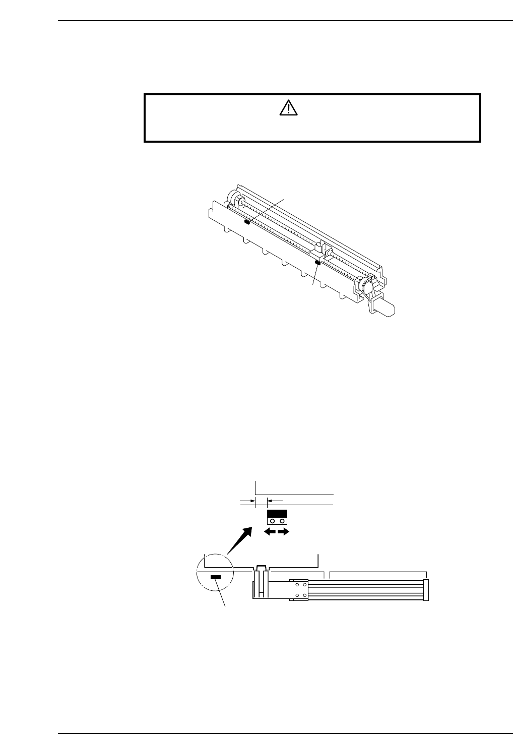
Pallet-position confirmation sensors are located on the in-side and the out-side.
In Pallet-position Confirmation Sensor
1. Move a pallet to the pallet IN-position.
The pallet IN-position is the fully advanced end of the pallet feed cylinder in setup
station in-side.
2. As shown in the figure below, align the sensor at a position 10 mm inward from
the edge of the pallet and secure it in place.
3. Adjust the sensor amp dial to "MIN."
Out Pallet-position Confirmation Sensor
Adjust in the same way as for the in pallet-position confirmation sensor.
10 mm
In pallet-position confirmation sensor
Pallet
CP6M9005
In pallet-position confirmation sensor
Out pallet-position confirmation sensor
CP6M9004
Part 8 Chapter 2 D-Axis Carrier
Edition 1.0 8-2-3 CP-6-series Mechanical Reference

Notes:
Part 8 Chapter 2 D-Axis Carrier
Edition 1.0 8-2-4 CP-6-series Mechanical Reference

3. Setup Station
There are a IN setup station and a OUT setup station. Each is driven by a pneumatic
cylinder to transport pallets.
In addition, a setup station carrying a pallet slides toward the rear of the machine, where
feeders can be loaded or removed more easily.
3.1 Adjustment of the Clamp-Area Sensors
Warning
Turn off the 200 V servo power before carrying out this work.
This adjustment is carried out in the same way as for the clamp area of the D-axis carrier.
Refer to Chapter 2 “D-Axis Carrier" of this part.
(ON)
(ON)
(OFF)
(OFF)
(ON)
(ON)
21.0 mm±1.0
Lowest position of the slider
CP6M9008
CP6M9007
Shock absorber Shock absorber
Pallet
Pneumatic cylinder
CP6M9006
Part 8 Chapter 3 Setup Station
Edition 1.0 8-3-1 CP-6-series Mechanical Reference