CP-6-series Mechanical Reference.pdf - 第282页
Notes: Part 8 Chapter 8 Checking the Operation of Solenoid V alves Edition 1.0 8-8-2 CP-6-series Mechanical Reference
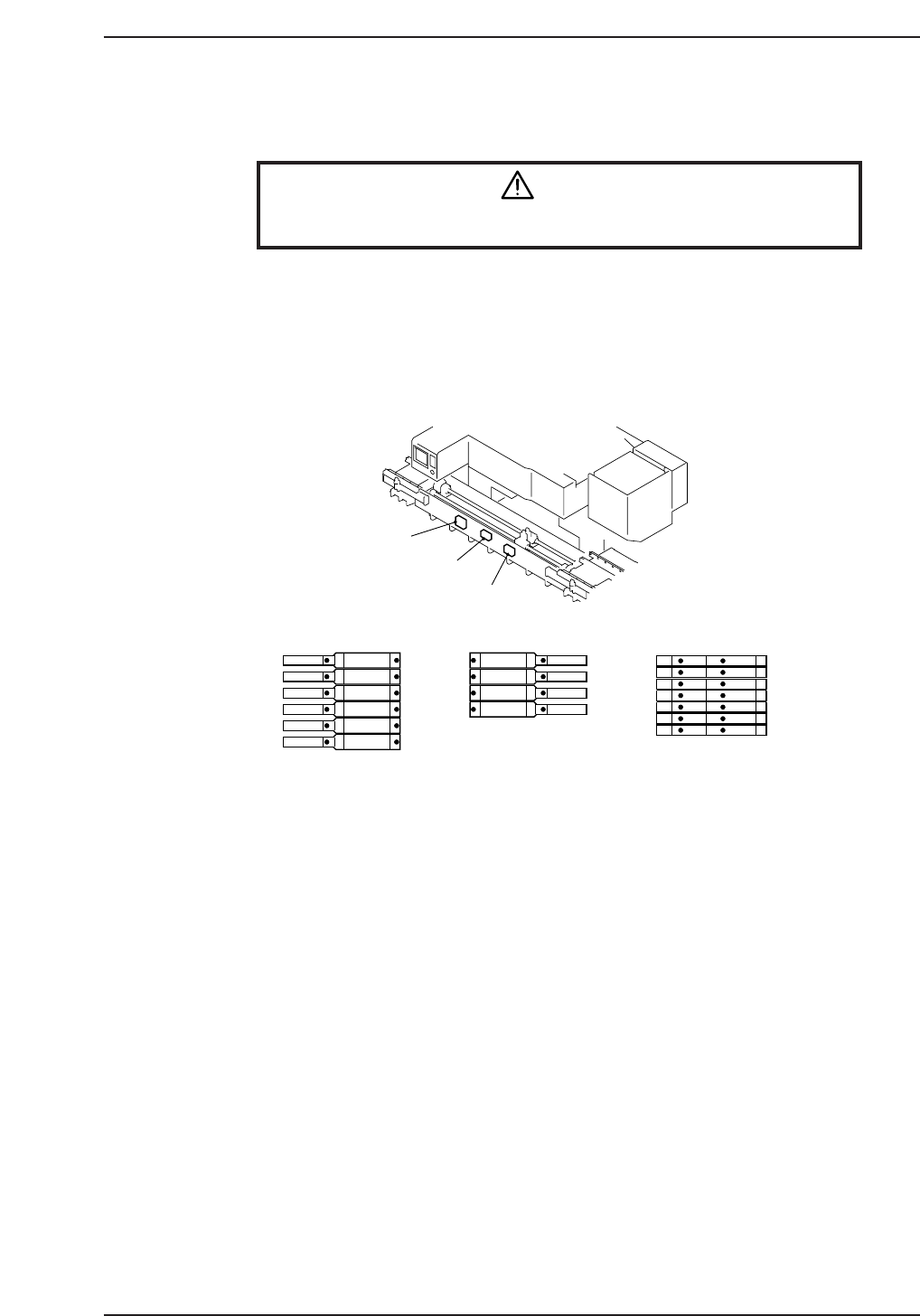
8. Checking the Operation of the Solenoid Valves
Warning
Turn off the 200 V servo power before carrying out this work.
Press the button on the solenoid valve using your finger to make sure that the various
parts operate correctly.
Note: Before performing this confirmation, be sure to press the EMERGENCY STOP button.
Before attempting to move the setup station forward or backward by hand, make sure there
is no interference with the position of the pallet feed cylinder or the pallet ejection cylinder.
1
2
3
4
5
6
7
8
9
10
11
12
13
14
15
16
17
1 PAL. IN TRAN. RET. / ADV.
2 UP LIFTER GATE&SHUT.
CLOSE
/
OPEN
3 PAL. OUT TRAN. ADV. / RET.
4 R.C. STOPPER OFF / ON
5 R.C. OUT TRAN. ADV. / RET.
6 R.C. IN TRAN. ADV. / RET.
7 SET UP St. IN SHIFT ADV. / RET.
8 SET UP St. IN PALET TRAN. RET. / ADV.
9 SET UP St. OUT SHIFT ADV. / RET.
10 SET UP St. OUT PALET TRAN. RET. / ADV.
11 DF CARRIER ON / OFF
12 DR CARRIER ON / OFF
13 SET UP St. IN STOPPER ON / OFF
14 UP LIFTER OUT STOPPER OFF / ON
15 UP LIFTER PAL. STOPPER OFF / ON
16 SET UP St. IN CLAMP ON / OFF
17 SET UP St. OUT CLAMP ON / OFF
✽
R.C.=Return conveyor
Solenoid Valves A
Solenoid Valves A
Solenoid Valves B
Solenoid Valves B
Solenoid Valves C
Solenoid Valves C
CP6M9044
Part 8 Chapter 8 Checking the Operation of Solenoid Valves
Edition 1.0 8-8-1 CP-6-series Mechanical Reference

Notes:
Part 8 Chapter 8 Checking the Operation of Solenoid Valves
Edition 1.0 8-8-2 CP-6-series Mechanical Reference

Part 8 Chapter 9 Adjustment of the Speed Controllers
Edition 1.0 8-9-1 CP-6-series Mechanical Reference
9. Adjustment of the Speed Controllers
Warning
Turn off the 200 V servo power before carrying out this work.
Note: The speed controllers are adjusted prior to the shipment of the machine. Cycle time can be
adversely effected or parts may not be fed correctly if these setting are not correct.
The settings should therefore not be changed by the user unless there is a particular need
to do so.
For reference purposes, this section describes the adjustment values of the speed
controllers for the various actuators.
Cycle time signifies the time required for a pallet to make one full circuit through the
pallet circulating machanism. When measuring the interval after a certain signal within
the feeder has been switched on until it is switched on again, the measured value must
be within the range of the established reference value.
Adjustment values are as follows. Pallets are assumed to be circulated in the normal
forward direction.
The numerical values in the table are the number of times of closure after being fully
opened.
D-axis carrier
IN pallet
IN stopper pallet
OUT pallet
IN return conveyor
OUT return conveyor
"UP" liffter pallet clamp
Setup station pallet clamp
Setup station pallet feed
Setup station table forward/backward
"UP" lifter gate
"UP" lifter out stopper
ON or Advance
6
3.5
3
3.5
2
2
Fully open
Fully open
4
3 (pushing)
4 (raising)
Fully open
OFF or retraction
Fully open
2.5
Fully open
Fully open
Fully open
Fully open
Fully open
Fully open
4
2.75 (pulling)
5 (lowering)
Fully open
CP6M9045