CP-6-series Mechanical Reference.pdf - 第301页
4.1.2 Adjusting the Sensor Position W ARNING Never look directly into the laser beam as this can damage the eyes. 1. Perform the following command sequence to move the main table to the loading position: [LOADER] - [LOAD…
4.1.1 Safety Measures
• Laser emission indicator lamp
The amplifier is equipped with an LED lamp which indicates when a laser beam is
being emitted. The operator can see that this LED is on even when wearing
protective goggles.
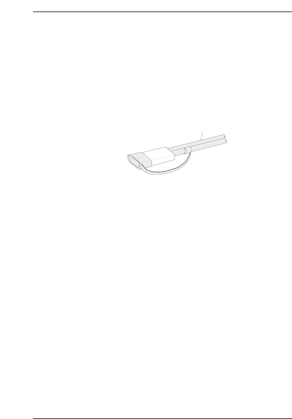
• Laser beam shield
A laser beam shield which can be attached to the fiber unit is supplied with FS-L
series sensors. Be sure to attach this shield when the operator must work in front of
the fiber unit where there is a risk of eye injury caused by the laser beam.
• Stopping the laser emission
Laser beam emission is stopped when the fiber unit is disconnected from the
amplifier unit.
Fiber unit
Laser beam shield attached
CP6M10019
Part 9 Chapter 4 Main Conveyor
Edition 1.0 9-4-3 CP-6-series Mechanical Reference
4.1.2 Adjusting the Sensor Position
WARNING
Never look directly into the laser beam as this can damage the eyes.
1. Perform the following command sequence to move the main table to the loading
position: [LOADER] - [LOADING PSTN] - START button.
2. Press the EMERGENCY STOP button to cut off the 200V power. Only the 100V
power should remain on.
WARNING
Turn off the 200 V servo power before carrying out this work.
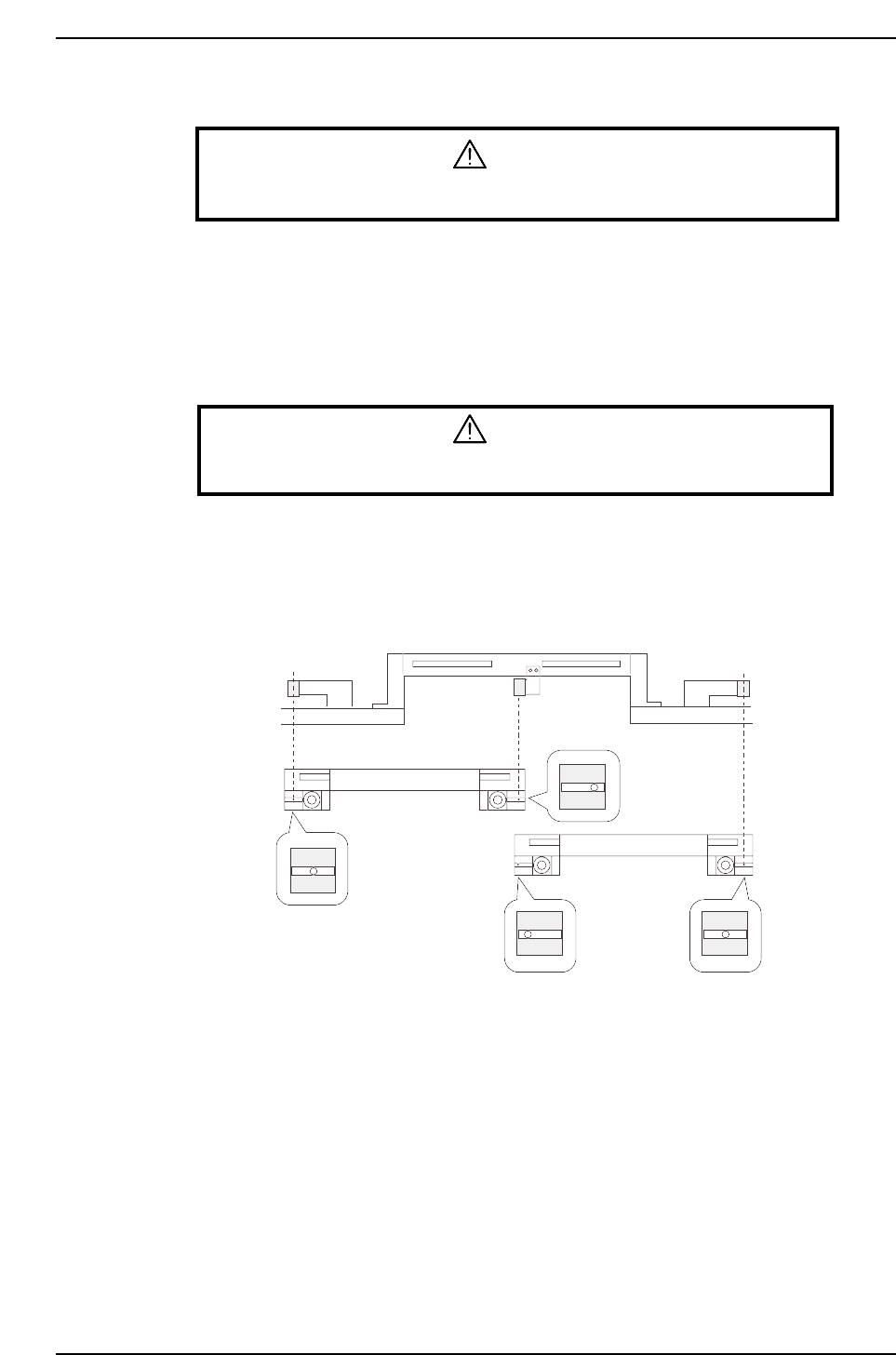
3. With the main conveyor’s adjustable rail engaged with the in- and out-conveyors’
adjustable rails, secure the sensor at the position where the seal’s silver area can be
detected.
Adjustable rail engagement
sensor 1
Adjustable rail engagement
sensor 2 Adjustable rail engagement
sensor 3
CP6M10020
(Toward the right)
(Center)
(Toward the left)
(Center)
IN loading
position
OUT loading
position
Part 9 Chapter 4 Main Conveyor
Edition 1.0 9-4-4 CP-6-series Mechanical Reference
4.1.3 Adjusting the Sensor Sensitivity (Amplifier Unit)
WARNING
Never look directly into the laser beam as this can damage the eyes.
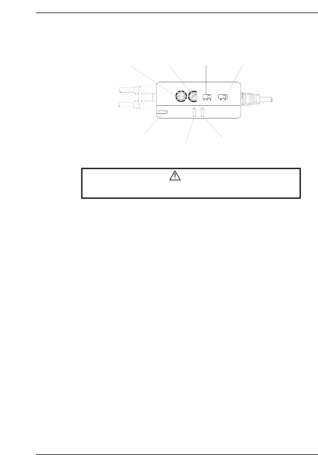
1. Set the timer setting trimmer to 40 ms, the timer mode selector switch to OFF, and
the operation mode selector switch to the “L ON” mode.
2. Adjust the sensitivity adjusting trimmer (SENS) until the following conditions are
obtained:
When the laser beam is striking the seal’s silver area at the adjustable rail, the
operation indicator (OUT) (red) and the stable operation indicator (STB) (green)
should be ON.
When the laser beam is striking the seal’s black area, the operation indicator (OUT)
(red) and the stable operation indicator (STB) (green) should be OFF.
3. Check the sensor inputs at the I/O screen using the following command sequence:
[I/O] - [Standard I/O] - [IN].
X034 FLWUP RAIL OUT
X035 FLWUP RAIL IN
Timer mode
selector switch
Operation mode
selector switch
Timer setting
trimmer
Sensitivity adjusting
trimmer
Laser emission indicator
Operation indicator
Stable operation indicator
L ON
D ON
MODE
OFF
ON D
OFF D
5s
TIMER
40ms
SENS
LASER
ON
STB
OUT
CP6M10021
Part 9 Chapter 4 Main Conveyor
Edition 1.0 9-4-5 CP-6-series Mechanical Reference