CP-6-series Mechanical Reference.pdf - 第307页
6.1 Adjustment of the Lifter Air Cylinder Sensors W ARNING • Turn off the 200 V servo power before carrying out this work. • The CP-643E/643ME conveyor is equipped with laser sensors. In areas where there is a risk of ey…
6. Out-Conveyor
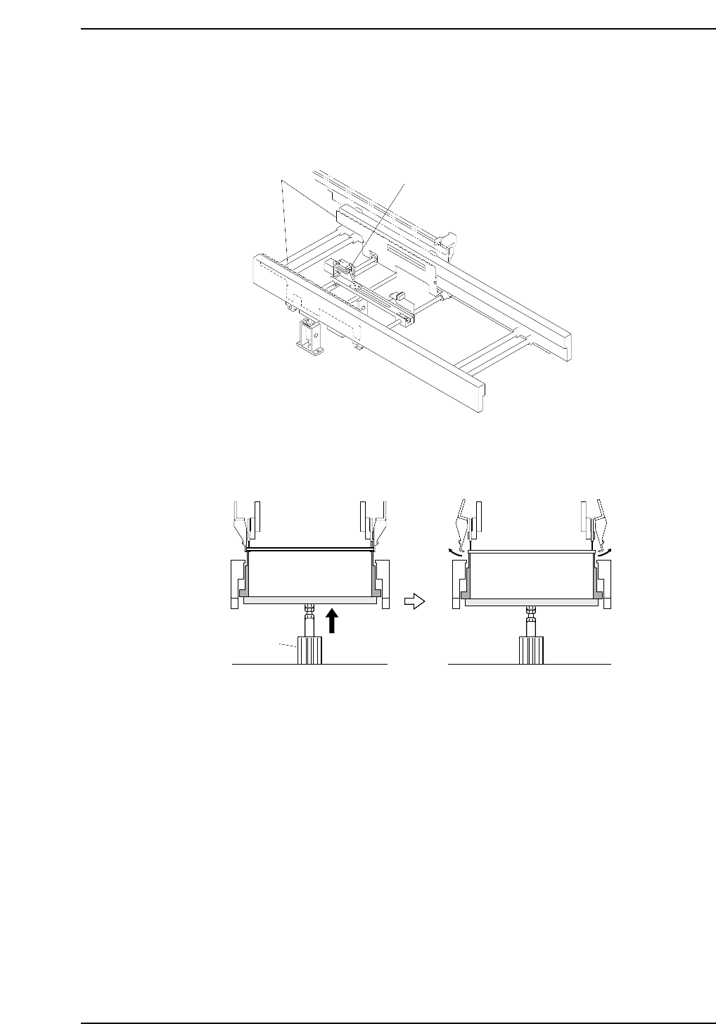
In addition to the guide rails, T-type conveyor belts, and motor that the standard
conveyor is equipped with, the out-conveyor in this system is also configured with a
lifter and mid-stopper.
The out-carrier retracts to the out-conveyor with boards clamped on the out-carrier. The
lifter is raised by means of an air cylinder and boards are received.
CP6M10030
Air cylinder
CP6M10029
Lifter
Mid-stopper
Part 9 Chapter 6 Out-Conveyor
Edition 1.0 9-6-1 CP-6-series Mechanical Reference
6.1 Adjustment of the Lifter Air Cylinder Sensors
WARNING
• Turn off the 200 V servo power before carrying out this work.
• The CP-643E/643ME conveyor is equipped with laser sensors.
In areas where there is a risk of eye damage from the laser beams,
be sure to install a laser beam shield at the laser emission area
before performing this sensor adjustment procedure.
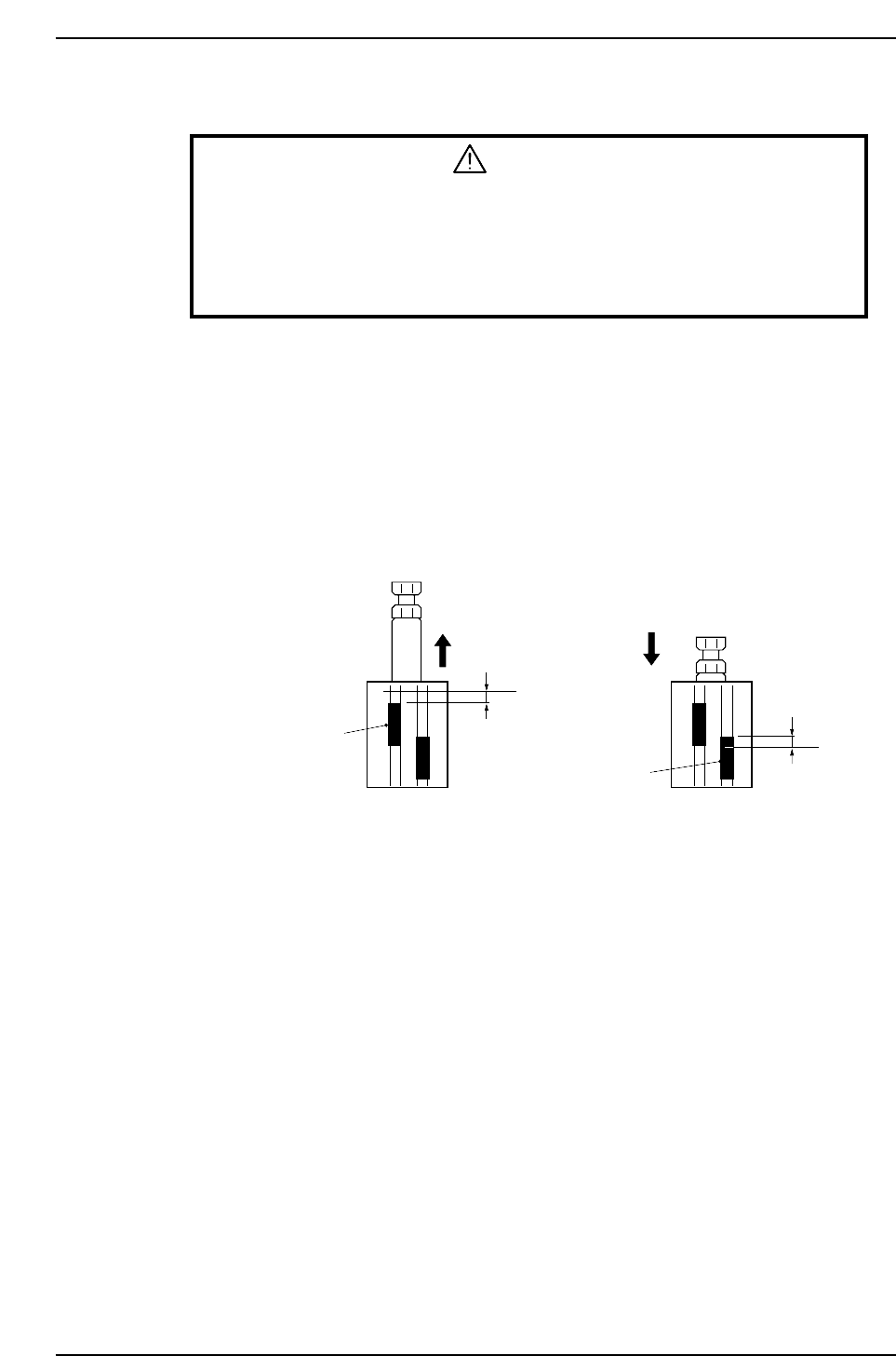
1. Release the air inside the cylinder.
2. Raise the lifter, set the cylinder in the extended status and check the position at
which the upper limit sensor comes ON.
3. From the position at which the sensor comes ON, lower the upper limit sensor by
0.5 mm and secure it in place.
4. Lower the lifter, set the cylinder in the contracted status, and check the position at
which the lower limit sensor comes ON.
5. From the position at which the sensor comes ON, raise the lower limit sensor by
0.5 mm and secure it in place.
a
b
Upper limit sensor
Lower limit sensor
0.5 mm
0.5 mm
CP6M10031
a: Position at which the upper limit sensor comes ON with the cylinder in the extended status
b: Position at which the lower limit sensor comes ON with the cylinder in the contracted status
Part 9 Chapter 6 Out-Conveyor
Edition 1.0 9-6-2 CP-6-series Mechanical Reference
6.2 Mid-Stopper Position Alignment
When a double board production program is executed, the second board must remain
stopped on the out-conveyor until the first board is unloaded from the machine. The
mid-stopper position must be set in order to stop the second board at the correct
position.
WARNING
• Turn off the 200 V servo power before carrying out this work.
• The CP-643E/643ME conveyor is equipped with laser sensors.
In areas where there is a risk of eye damage from the laser beams,
be sure to install a laser beam shield at the laser emission area
before performing this sensor adjustment procedure.
1. When there are no boards on the out-conveyor, confirm that the following
responses are returned from the three sensors listed below.
• First board check sensor OFF
• Second board check sensor OFF
• Gap check sensor ON
2. Put boards on the out-conveyor that are the maximum size for double board
transport (X-direction 220 mm). Confirm that the gap check sensor goes OFF
when a board is over the gap check sensor.
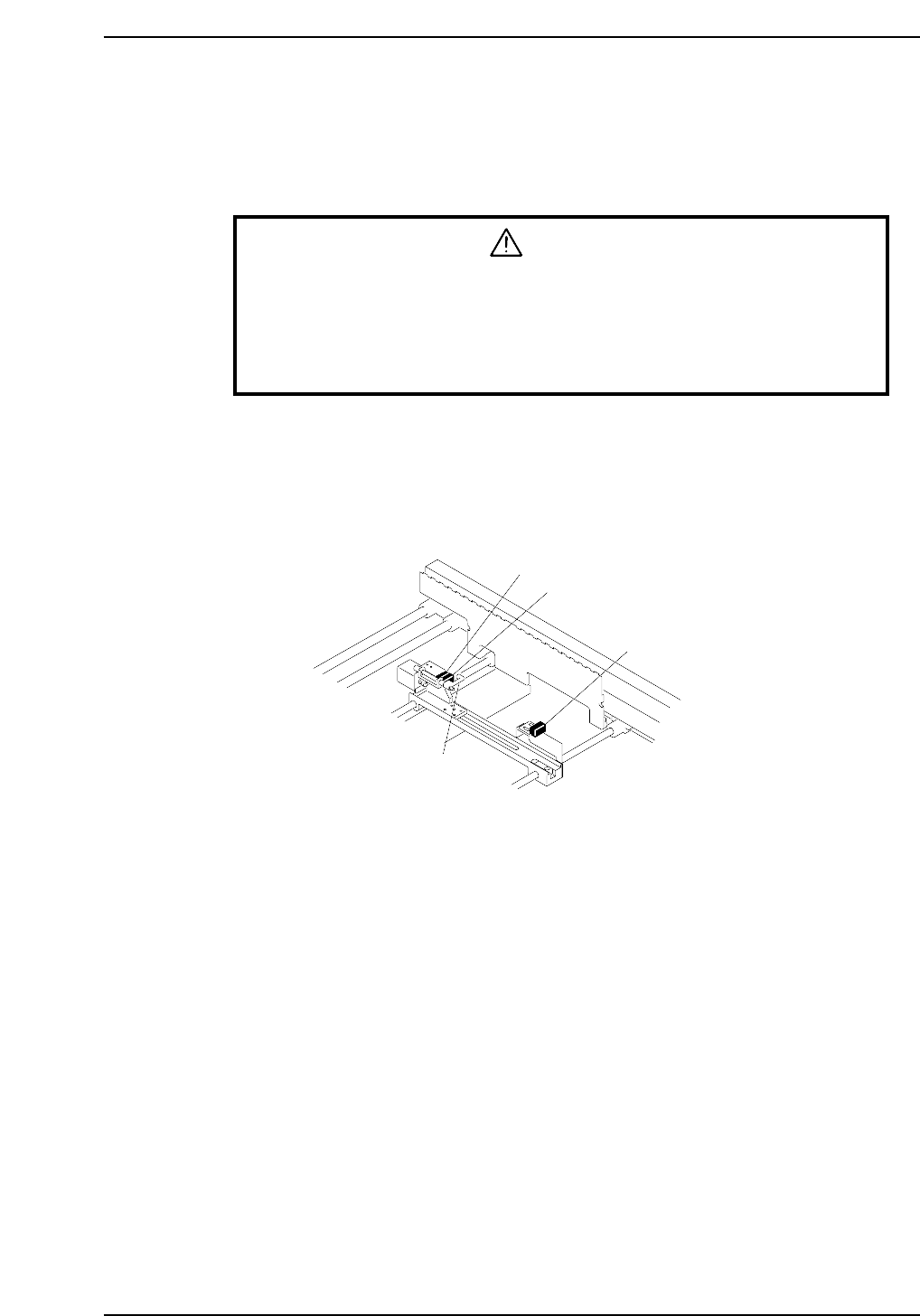
3. Adjust the first board check sensor position such that the following conditions are
satisfied.
• First board check sensor comes on at a position 5.0 mm from the front edge of
the board.
• Gap check sensor is ON (no board over the sensor).
4. Raise the mid-stopper (I/O LY006 ON), and adjust the position of the second
board check sensor mounting bracket such that the distance between the front
edge of the second board on the out-conveyor and the mid-stopper is from 0.2 to
0.3 mm.
CP6M10032
First board check sensor
Second board check sensor
Gap check sensor
Mid-stopper
Part 9 Chapter 6 Out-Conveyor
Edition 1.0 9-6-3 CP-6-series Mechanical Reference