CP-6-series Mechanical Reference.pdf - 第327页
Notes: Appendix B. Directions for Use Edition 1.0 B-2 CP-6-series Mechanical Reference
B. Directions for Use
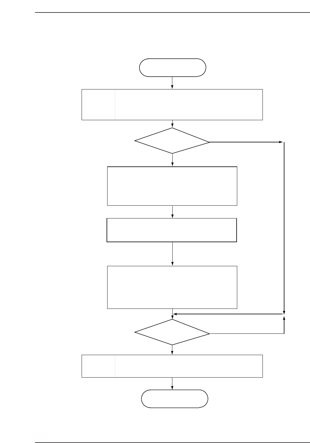
Start
When the supply power to the OILMATIC turns
"ON", the current oil temperature will be indicated,
RUN lamp lights on, and operation starts.
Start-up
Change
set temperature?
When "Para" switch is pressed, "0" will be
indicated on the parameter indicating LED and
current set temperature on the DATA
indicating LED.
Target temperature set by pressing "UP"
switch or "DOWN" switch.
Fluid temperature set range is 5.0 to
40.0 °C in 0.1 °C increments.
Holding down the "PV" switch will display the
current oil temperature.
Fluid temperature control settings may be
changed here.
Stop
operation?
Stop
When the power supply to the OILMATIC is
cut, the OILMATIC stops operating.
Stop
Yes
Yes
No
No
CP6MA003
Appendix B. Directions for Use
Edition 1.0 B-1 CP-6-series Mechanical Reference

Notes:
Appendix B. Directions for Use
Edition 1.0 B-2 CP-6-series Mechanical Reference

C. Troubleshooting
The OILMATIC is guaranteed to achieve optimum performance when operated under the correct
load with the correct power supply. If trouble arises, check the following table and take necessary
countermeasures.
1. Check the LEDs on the operation panel and identify the cause of trouble using the
table given below.
Operation of Lamp
RUN
●
(OFF)
●
❍
(ON)
PARA and DATA
LED Displays
Light OFF
AL00
Blink of "H"
and current
temperature
due to
temperature
rise
Cause
● Power is not being
supplied properly
● Circuit protector of
control circuit is blown
● Reverse phase protective
relay is activated.
● Connection failure or
broken wiring connection.
● Thermal protector B1
(THP) is activated and
then resets automatically.
● Temperature switch for
fluid temperature rise B3
(HTS) is activated.
● Refrigeration circuit
pressure switch B2 (GPS)
is activated.
● Thermal protector B1
(THP) is activated.
● Refrigeration
compressor thermal
relay F2 (OL2) is activated.
● Pump motor thermal
relay F1 (OL1) is activated.
● The sensor is
disconnected.
● Temperature controller
or temperature sensor is
broken.
● Low cooling capacity.
Countermeasure/Action
● Check the voltage between
terminals R, S and T in the
control box using a tester.
Replace circuit protector if
it is blown.
● Change the order of the
power phase.
● Check for connection failure
and breakage at all wiring
connections.
● Check if it is activated.
● Refer to the protective
devices.
● Check sensor connection.
● Replace with a new
OILMATIC
● Cooling capacity may
decrease due to the decrease
of heat exchanging capacity
if the oil circulation pressure
is too weak.
● Insufficient refrigerant
may cause poor cooling
capacity though not to the
extent of no-operation of
protective device.
CP6MA004
Appendix C. Troubleshooting
Edition 1.0 C-1 CP-6-series Mechanical Reference